
Building equipment energy flow network monitoring device

A technology for network monitoring and building equipment, applied in measuring devices, measuring electrical variables, instruments, etc., can solve the problems of inability to accumulate energy, difficult energy waste, inconvenient measurement, etc., and achieve the effect of preventing energy waste and convenient measurement

Inactive Publication Date: 2018-03-09
吴文学
View PDF0 Cites 3 Cited by
  • Summary
  • Abstract
  • Description
  • Claims
  • Application Information

AI Technical Summary

Problems solved by technology

[0006] In order to overcome the shortcomings of the existing energy flow monitoring that cannot accumulate energy, is inconvenient to measure, and is difficult to prevent energy waste in time, the technical problem to be solved by the present invention is to provide a method that can accumulate energy, measure conveniently, and can be timely Network monitoring device for energy flow of building equipment to prevent energy waste

Method used


Image

  • Building equipment energy flow network monitoring device

Examples


Embodiment 1

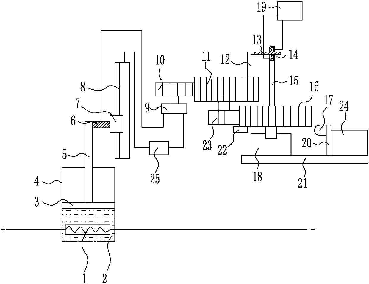
[0016] A network monitoring device for energy flow of building equipment, such as figure 1 As shown, it includes heating wire 1, paraffin wax 2, piston 3, cavity 4, lifting rod 5, connecting block 6, sliding block 7, sliding rheostat 8, motor 9, first small gear 10, first large gear 11, Rotating rod 12, contact shrapnel 13, contact block 14, fixed rod 15, second large gear 16, button 17, bearing seat 18, monitor 19, pole 20, fixed plate 21, pressure block 22, second pinion 23 , alarm 24 and power supply 25, a heating wire 1 is provided at the inner bottom of the cavity 4, paraffin wax 2 is installed at the inner bottom of the cavity 4, the left end of the heating wire 1 is connected with a positive line, and the right end of the heating wire 1 is connected with a negative line, the cavity 4 There is a piston 3 inside, the piston 3 cooperates with the cavity 4, the top of the piston 3 is provided with a lifting rod 5, the top right side of the lifting rod 5 is provided with a c...


PUM


Abstract

The invention involves a network monitoring device, especially a network monitoring device that involves a construction equipment energy flow.The technical problem to be solved by the present invention is to provide a network monitoring device that can accumulate energy, conveniently measure, and timely prevent energy flow of energy waste.Small gears, the first gear, rod, etc.; The bottom of the cavity is equipped with electric heating wire, paraffin is equipped with the bottom of the cavity, the left end of the electric heating wire is connected to the positive pole line, the right end of the electric heating wire is connected to the negative electrode line.Cooperate with the cavity, the top of the piston has a lifting rod.The invention has achieved the effect of accumulating energy, convenient measurement, and timely preventing energy waste.

Description

technical field [0001] The invention relates to a network monitoring device, in particular to a network monitoring device for energy flow of construction equipment. Background technique [0002] The network monitoring, evaluation and optimization method of building equipment energy flow uses coupling optimization technology to evaluate the efficiency of regional energy use. Use energy consumption as an important optimization index to evaluate the efficiency of regional energy use, and establish an energy dispatching system; monitor, analyze and evaluate based on energy flow networks; establish an expert system for diagnosing abnormal energy consumption. Predict the energy consumption of each process or the comprehensive energy consumption per unit of energy based on the annual, quarterly, and monthly planning data of building use, as well as historical energy performance data and climate data. Using intelligent budget algorithms such as linear regression, neural network, an...

Claims


Application Information

Patent Timeline
Patent Type & Authority Applications(China)
IPC IPC(8): G01R22/04
CPCG01R22/04
Inventor 吴文学
Owner 吴文学
Learn More