

Argon arc welding gas shield throttling control device
A gas shielding and throttling control technology, which is used in devices for supplying/removing shielding gas, arc welding equipment, manufacturing tools, etc., can solve the problems of resource waste, gas loss, improper argon flow control, etc., to prevent waste of resources , to ensure the effect of sealing
- Summary
- Abstract
- Description
- Claims
- Application Information
AI Technical Summary
Problems solved by technology
Method used
Image

Examples
Embodiment 1
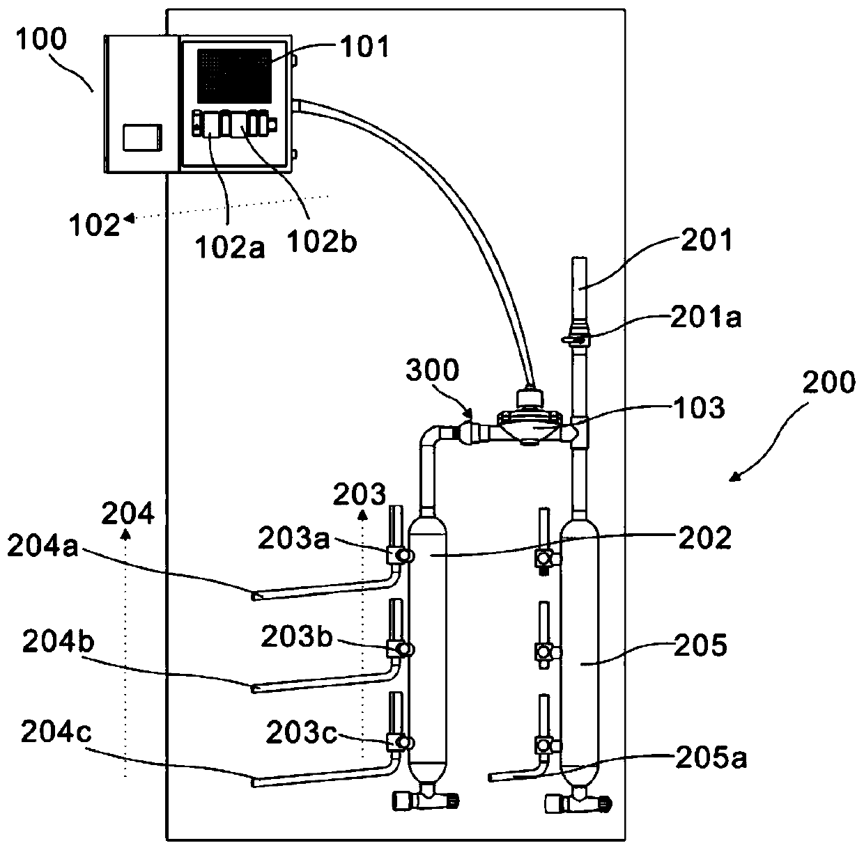
[0028] refer to figure 1 and figure 2 , the present invention provides a gas protection throttling control device for argon arc welding, including an electric control assembly 100 and a gas passage 200, wherein the electric control assembly 100 includes a switching power supply 101, a delay element 102 and a solenoid valve 103, and the switching power supply 101 Connect the delay piece 102, the solenoid valve 103 is connected with the switching power supply 101 through the delay piece 102; the gas passage 200 includes an intake pipe 201, an argon storage bag 202, a flow meter 203 and an air supply pipe 204, and the solenoid valve 103 is arranged on the intake pipe Between 201 and the argon gas storage bag 202, the flow meter 203 is connected to the argon gas storage bag 202 and the gas supply pipe 204, and the gas supply pipe 204 is connected to the welding torch Y.
[0029] In this embodiment, the device is used for the protective throttling control of the inert gas used by...
Embodiment 2
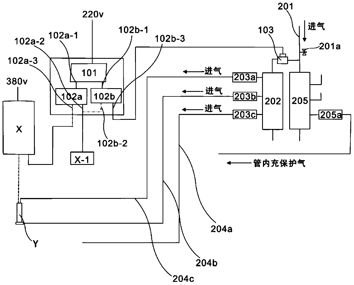
[0033] refer to figure 1 and figure 2 The difference between this embodiment and the previous embodiment is that the delay element 102 includes a power-on delay relay 102a and a power-off delay relay 102b. The electric time delay relay 102b is electrically connected with the solenoid valve 103 . The power-on delay relay 102a includes a first control terminal 102a-1, and the power-off delay relay 102b includes a second control terminal 102b-1. Both the first control terminal 102a-1 and the second control terminal 102b-1 are connected to the switching power supply 101.
[0034]The power-on delay relay 102a also includes a first on-off terminal 102a-2, and the power-off delay relay 102b also includes a second on-off terminal 102b-2, and the first on-off terminal 102a-2 and the second on-off terminal 102b- 2 connections. The power-on delay relay 102a also includes a third on-off terminal 102a-3, and the power-off delay relay 102b also includes a fourth on-off terminal 102b-3. ...
Embodiment 3
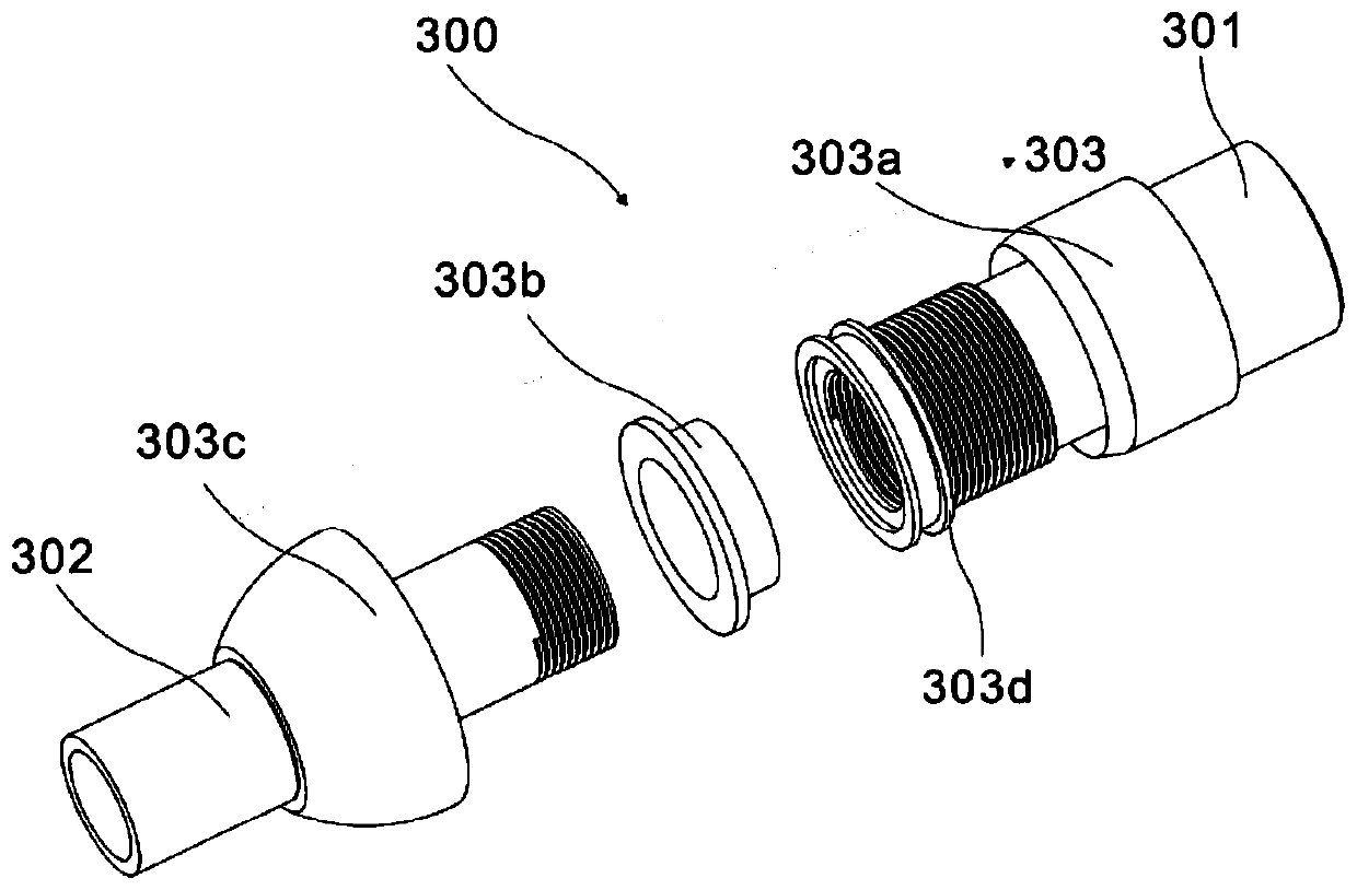
[0040] refer to image 3 and 4 The difference between this embodiment and the previous embodiment is that a connection structure 300 is provided at the connection between the end of the solenoid valve and the pipeline, and the connection structure 300 is used to seal the connection between the solenoid valve 103 and the short knife to prevent Insufficient sealing after connection causes gas leakage and wastes resources. The connection structure 300 includes a connecting pipe 301 arranged on the solenoid valve 103, a gas pipeline 302 connected to the solenoid valve 103, and a seal 303 arranged at the joint between the connecting pipe 301 and the gas pipeline 302, and the seal 303 includes a sealing sleeve 303a , Built-in washer 303b, locking screw 303c and sealing ring 303d, sealing sleeve 303a is arranged on the connecting pipe 301, built-in gasket 303b and locking screw 303c are arranged on the gas pipeline 301, sealing ring 303d is arranged on the connecting pipe 301 and b...
PUM
 Abstract
Description
Claims
Application Information