Supercharge Your Innovation With Domain-Expert AI Agents!

Reactive arm for mechanical control

A mechanical control and reaction technology, applied in non-electric variable control, position/direction control, control/regulation system, etc., can solve the problems of contact error of the reaction arm, inconvenience of the reaction arm, unfavorable promotion, etc., to reduce the number of , Simple structure, easy to use effect

Inactive Publication Date: 2018-03-09
天津市泓金泰特种机械有限公司
View PDF9 Cites 0 Cited by
  • Summary
  • Abstract
  • Description
  • Claims
  • Application Information

AI Technical Summary

Problems solved by technology

[0002] At present, in the field of mechanical control, it is usually controlled by hydraulic equipment. At present, it is very difficult for the hydraulic equipment to accurately control the stroke of the hydraulic piston, or the angle of the lever pushed by the piston stroke. It requires the operator to be quite familiar with the machinery and quite skilled. , there are also some foreign equipment that use electronics to accurately and quickly control their travel by computer methods. The cost is naturally very expensive and is not conducive to promotion. In the process of mechanical control, the reaction arm is an indispensable part. The reaction arm is usually Receive the action signal from the control arm, complete the action command sent by the control arm, and constantly touch the travel switch to complete the control of the working arm. However, the existing reaction arm usually only has two contacts and the stroke is fixed. If it is necessary to complete complex formation control, it is necessary to increase the number of reaction arms, and usually only one contact point of the reaction arm works, increasing the number of reaction arms will not only cause inconvenience in the control of the reaction arm, but also cause contact errors of the contact points of the reaction arm Case

Method used


Image

  • Reactive arm for mechanical control
  • Reactive arm for mechanical control

Examples


Embodiment Construction

[0017] It should be noted that, in the case of no conflict, the embodiments of the present invention and the features in the embodiments can be combined with each other.

[0018] The present invention will be described in detail below with reference to the accompanying drawings and examples.

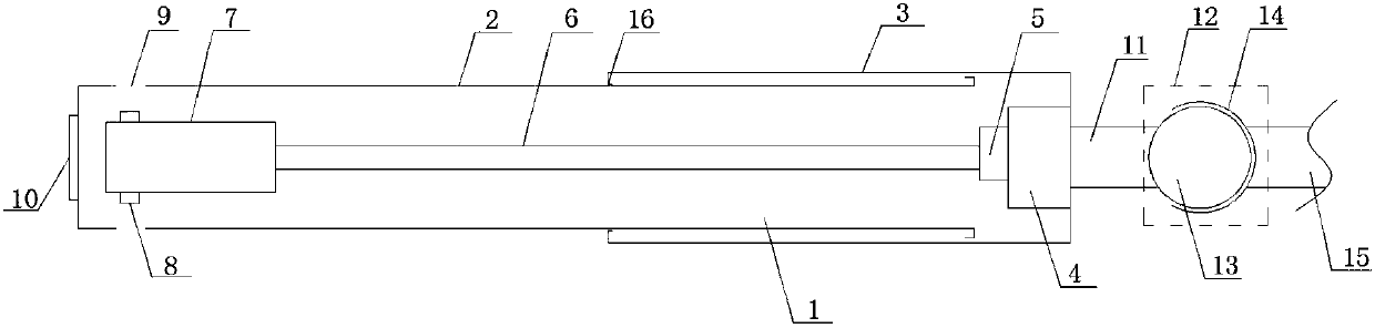
[0019] Such as figure 1 and figure 2 As shown, a reaction arm for mechanical control includes an arm body 1, a connecting rod 11 and a fixed rod 15, the arm body 1 includes a socketed first arm 2 and a second arm 3, the first arm The end of a branch arm 2 and the top end of the second branch arm 3 are provided with baffles 16, which can prevent the first arm body 2 from breaking away from the second arm body 3 during the elongation process. The arm 3 is fixedly connected with the connecting rod 11, the inner end of the second sub-arm 3 is provided with a support platform 4, and the support platform 4 is provided with a universal joint 5, and the support platform 4 passes through the u...


PUM


Abstract

The invention provides a reaction arm for mechanical control, comprising an arm body, a connecting rod and a fixed rod, wherein the arm body comprises a first sub arm and a second sub arm sleeved witheach other, the second sub arm is fixedly connected with the connecting rod, a support table is arranged at the inner end of the second sub arm, a universal joint is arranged on the support table, the support table is connected with a telescopic rod through the universal joint, a contact table is arranged at the end of the telescopic rod, a contact is arranged on the contact table, the first subarm is hollowed, the hollowed position corresponds to the contact, and the connecting rod is connected with the fixed rod through a spherical connector. According to the reaction arm for mechanical control, the first sub arm and the second sub arm are sleeved with each other, so that the overall length of the arm body can be adjusted, and the reaction arm can adapt to more use environments. The contact is arranged inside the arm body, so that only one contact is exposed when the reaction arm works, and inadvertent contact caused by simultaneous exposure of a few contacts is prevented. The armbody is driven by the spherical connector to rotate, so that the movement stroke direction of the arm body can be enlarged.

Description

technical field [0001] The invention belongs to the technical field of mechanical connectors, and in particular relates to a reaction arm for mechanical control. Background technique [0002] At present, in the field of mechanical control, it is usually controlled by hydraulic equipment. At present, it is very difficult for the hydraulic equipment to accurately control the stroke of the hydraulic piston, or the angle of the lever pushed by the piston stroke. It requires the operator to be quite familiar with the machinery and quite skilled. , there are also some foreign equipment that use electronics to accurately and quickly control their travel by computer methods. The cost is naturally very expensive and is not conducive to promotion. In the process of mechanical control, the reaction arm is an indispensable part. The reaction arm is usually Receive the action signal from the control arm, complete the action command sent by the control arm, and constantly touch the travel...

Claims


Application Information

Patent Timeline
IPC IPC(8): G05D3/00H01H3/16
CPCG05D3/00H01H3/16
Inventor 汪衍
Owner 天津市泓金泰特种机械有限公司
Features
  • R&D
  • Intellectual Property
  • Life Sciences
  • Materials
  • Tech Scout
  • Unparalleled Data Quality
  • Higher Quality Content
  • 60% Fewer Hallucinations
Learn More