Method and device for establishing path

A path and optical path technology, applied in the field of communication, can solve the problem of not providing a centralized path calculation distributed signaling solution for the control plane, etc.

Active Publication Date: 2018-03-09
ZTE CORP
View PDF5 Cites 1 Cited by
  • Summary
  • Abstract
  • Description
  • Claims
  • Application Information

AI Technical Summary

Problems solved by technology

The industry does not provide solutions for centralized p...

Method used


Image

  • Method and device for establishing path
  • Method and device for establishing path
  • Method and device for establishing path

Examples


Embodiment Construction

[0065] In order to understand the characteristics and technical contents of the embodiments of the present invention in more detail, the implementation of the embodiments of the present invention will be described in detail below in conjunction with the accompanying drawings. The attached drawings are only for reference and description, and are not intended to limit the embodiments of the present invention.

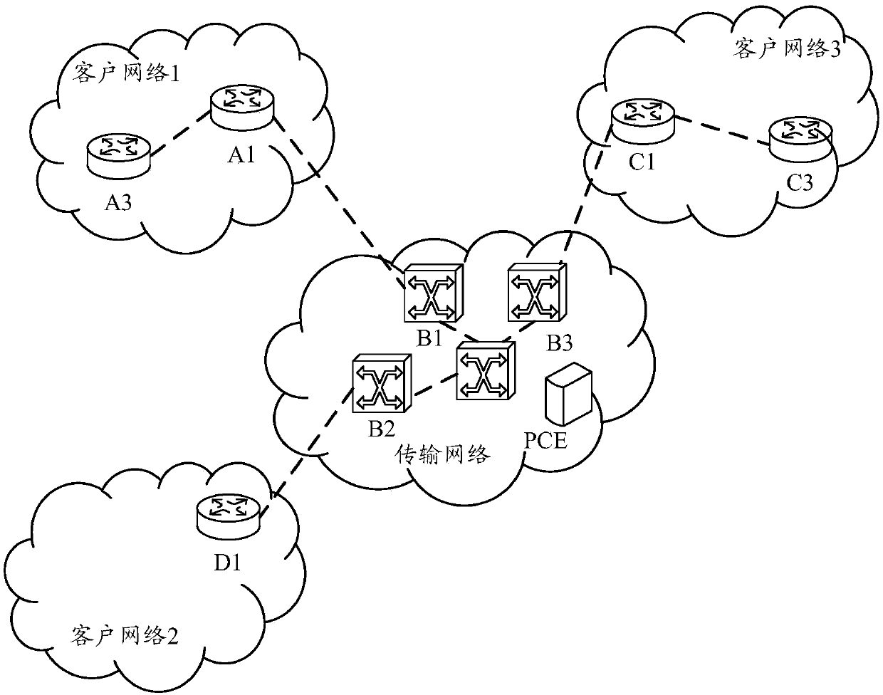
[0066] Figure 4 It is a schematic flowchart of a method for establishing a path in an embodiment of the present invention. The method for establishing a path in this example is applied in a PCE, such as Figure 4 As shown, the method for establishing a path includes the following steps:

[0067] Step 401: Obtain the color light port parameters of the client layer devices at both ends.

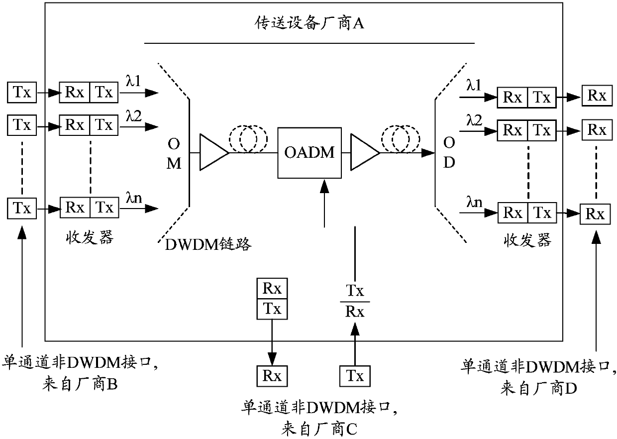
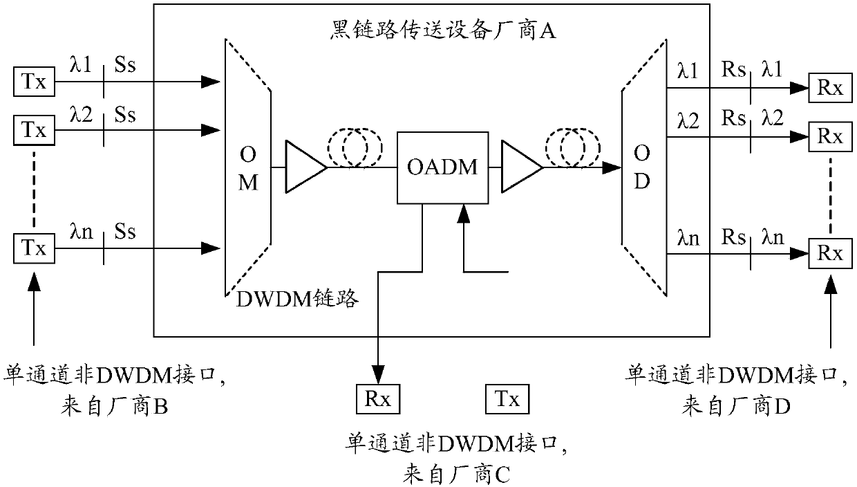
[0068] Here, the client layer equipment refers to a transmitter (Tx) and a receiver (Rx) from a certain manufacturer. The communication signal between the client layer device at one end...


PUM


Abstract

The invention discloses a method and device for establishing a path. The method comprises the steps that a path computation element obtains colorful light port parameters of client layer devices at two ends; a first optical path between two boundary nodes is established in an optical transport network domain according to parameter information of an optical transport network and an optical wavelength range supported by the client layer devices at the two ends; optical path parameters are obtained, and whether the optical path parameters satisfy a constraint condition of a black link of the optical transport network or not is determined; the first optical path is deleted if the constraint condition is not satisfied, and a second optical path is established until the optical path of which optical path parameters satisfy the constraint condition is established; whether parameters of black link ports of the client layer devices at the two ends satisfy a constraint condition range or not isjudged after the optical path of which optical path parameters satisfy the constraint condition is established; and the end-to-end optical path is determined for the client layer devices at the two ends if the constraint condition range is satisfied.

Description

technical field [0001] The present invention relates to the communication field, in particular to a method and device for establishing a path. Background technique [0002] In a traditional optical transport network (Transport Network), a client layer device (such as figure 1 The communication on the user network interface (UNI, User Network Interface) between the transmitter (Tx) and receiver (Rx) in manufacturer B and manufacturer D shown in ) and another client layer device at a distance Signals are carried by optical transport equipment. The equipment on the User Network Interface-Costumer (UNI-C, User Network Interface-Costumer) side is generally connected to the interface of the transmission network equipment through an optical port. On the User Network Interface-Network (UNI-N, User Network Interface-Network) side, the customer signal is transformed into a Dense Wavelength Division Multiplexing (DWDM, Dense Wavelength Division Multiplexing) wavelength that meets the...

Claims


Application Information

Patent Timeline
IPC IPC(8): H04Q11/00
CPCH04Q11/0005
Inventor 王其磊
Owner ZTE CORP
Why Eureka
Try Eureka