Passive ventilation device

A ventilation device, a passive technology, applied in space heating and ventilation, heating methods, lighting and heating equipment, etc., can solve the problem of unavailable active ventilators and achieve the effect of reducing fugitive infiltration

Pending Publication Date: 2022-07-01
CHINA NUCLEAR POWER ENG CO LTD
View PDF0 Cites 0 Cited by
  • Summary
  • Abstract
  • Description
  • Claims
  • Application Information

AI Technical Summary

Problems solved by technology

[0004] The technical problem to be solved by the present invention is to provide a passive ventilator for the above-mentioned deficiencies in the prior art, which solves the problem that the active ventilator is unavailable after power failure. On the basis of ventilation, the vortex tube is used to realize the function of simultaneously ensuring fresh air, ambient temperature, micro positive pressure and allowable concentration of pollutants in the habitable area

Method used


Image

  • Passive ventilation device

Examples


Embodiment 1

[0045] This embodiment provides a passive ventilation device, including:

[0046] Compressed air storage tanks for storing compressed air;

[0047] The vortex tube is connected to the compressed air storage tank. The vortex tube is used to generate vortexes from the compressed air to separate cold and hot air flows. The vortex tube includes a vortex tube body, a vortex tube hot end and a vortex tube cold end arranged on the vortex tube body. ;

[0048] The purification mechanism is connected to the hot end of the vortex tube, and the purification mechanism is used to purify the hot air flow separated from the hot end of the vortex tube to purify the air in the habitable area and then send it to the habitable area;

[0049] The ventilation mechanism is connected with the cold end of the vortex tube, and the ventilation mechanism is used to send the cold air flow separated from the cold end of the vortex tube into the habitable area to provide fresh air and cooling for the habi...

Embodiment 2

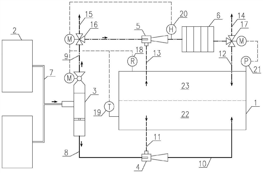
[0052] like figure 1 As shown, this embodiment provides a passive ventilation device, including:

[0053] Compressed air storage tank 2 for storing compressed air;

[0054] The vortex tube 3 is connected to the compressed air storage tank 2. The vortex tube 3 is used to separate the cold and hot air flows by generating a vortex of the compressed air. The vortex tube 3 includes a vortex tube body and a vortex tube 3 disposed on the vortex tube body. end, vortex tube 3 cold end;

[0055] The purification mechanism is connected to the hot end of the vortex tube 3, and the purification mechanism is used to purify the air in the habitable area 1 from the hot air flow separated from the hot end of the vortex tube 3 and then send it to the habitable area 1;

[0056] The ventilation mechanism is connected with the cold end of the vortex tube 3. The ventilation mechanism is used to send the cold air flow separated from the cold end of the vortex tube 3 into the habitable area 1, prov...


PUM


Abstract

The invention discloses a passive ventilation device which comprises a compressed air storage tank used for storing compressed air; the vortex tube is connected with the compressed air storage tank, the vortex tube is used for generating vortexes by the compressed air to separate cold airflow and hot airflow, and the vortex tube comprises a vortex tube body, a vortex tube hot end and a vortex tube cold end, and the vortex tube hot end and the vortex tube cold end are arranged on the vortex tube body; the purification mechanism is connected with the hot end of the vortex tube, and the purification mechanism is used for purifying air in the resident area through the hot airflow separated from the hot end of the vortex tube and then sending the purified air into the resident area; and the ventilation mechanism is connected with the cold end of the vortex tube, and the ventilation mechanism is used for feeding the cold air flow separated from the cold end of the vortex tube into the resident area, providing fresh air and cooling for the resident area and maintaining the positive pressure of the area. According to the ventilation device, compressed air is separated into cold air flow and hot air flow through the vortex tube, and power is provided for the ventilation mechanism and the purification mechanism through the pressure of the compressed air.

Description

technical field [0001] The invention belongs to the technical field of ventilation in the nuclear industry, and in particular relates to a passive ventilation device. Background technique [0002] When a radioactive pollution accident occurs outside the resident area of ​​nuclear power plant personnel and the normal AC power supply is lost at the same time, the active ventilation and purification system will not be able to operate. The radioactivity concentration of the air is below the limit. At present, in nuclear power plants, emergency power supplies are mostly used to supply power to the ventilation and purification systems after accidents. The power supply equipment includes fans, refrigeration equipment, and electric heaters. This method has complex design, high energy consumption, and there is still a certain risk of failure. [0003] In addition, there is a passive ventilation method, which uses compressed air storage tanks to provide fresh air and ventilation powe...

Claims


Application Information

Patent Timeline
Patent Type & Authority Applications(China)
IPC IPC(8): F24F5/00F24F11/64F24F11/74F24F11/89F25B9/04G21D1/00G21D1/02
CPCF24F5/0007F24F11/64F24F11/89F24F11/74F25B9/04G21D1/02G21D1/003
Inventor 胡北荆春宁王晓江李百利张丽丽刘婧康健
Owner CHINA NUCLEAR POWER ENG CO LTD
Why Eureka
Try Eureka