A tungsten inert gas welding protection device for turbine blades
A tungsten inert gas and protection device technology, applied in welding equipment, auxiliary devices, auxiliary welding equipment, etc., can solve the problems of easy occurrence of welding cracks and affect the processing quality of parts, and achieve the effect of improving welding quality and reducing manufacturing costs.
Active Publication Date: 2019-10-01
AECC AVIATION POWER CO LTD
View PDF7 Cites 0 Cited by
- Summary
- Abstract
- Description
- Claims
- Application Information
AI Technical Summary
Problems solved by technology
The purpose of the present invention is to provide a tungsten inert gas welding protection device for turbine blades, which solves the problem that only the inert gas flowing out of the welding torch is used to protect the parts when the welding part of the existing low-pressure turbine blade crown is welded, resulting in easy welding after welding. Cracks, defects that affect the processing quality of parts
Method used
View moreImage
Smart ImageViewing Examples
Examples
Embodiment Construction
Login to View More PUM
 Abstract
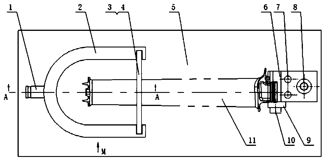
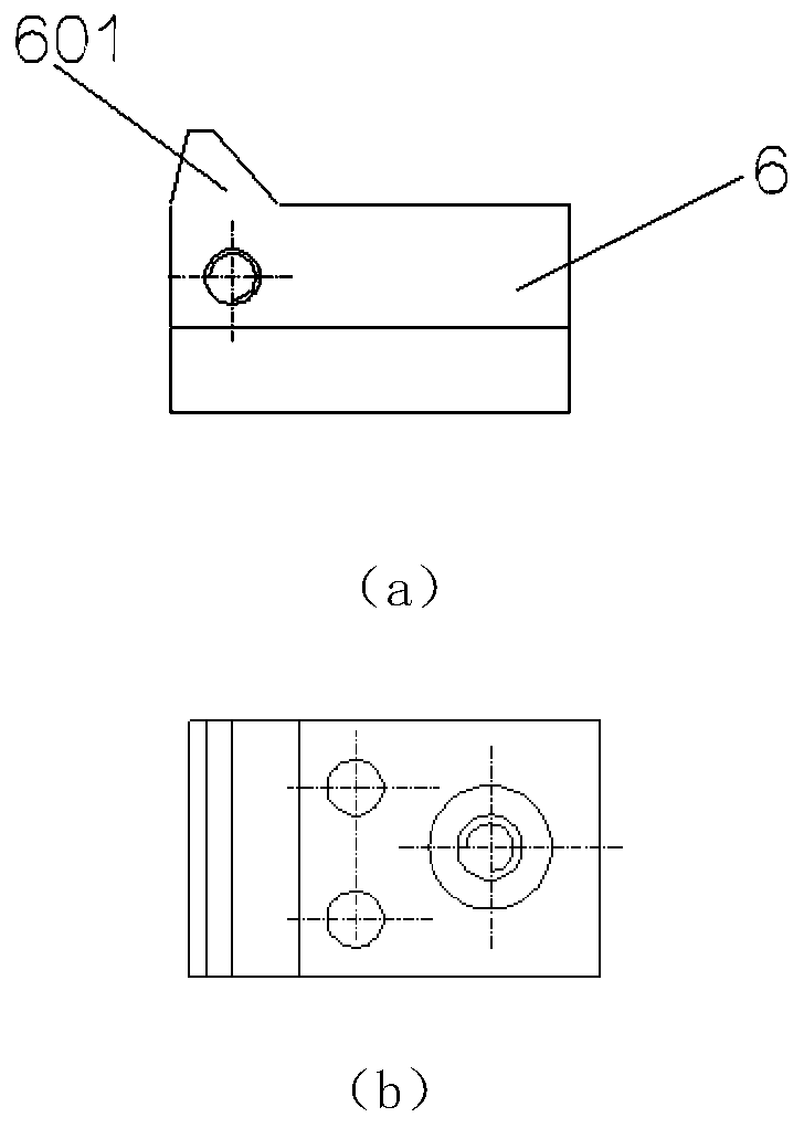
The invention provides a turbine blade tungsten electrode inert gas welding protective device. Firstly, a low-pressure turbine blade is placed on a bottom plate, the blade root part of the low-pressure turbine blade is fixed through a fixing device simultaneously, the condition that welding quality is influenced due to back-and-forth movement of a welded part during welding is prevented, finally the low-pressure turbine blade is placed in a protective shell with an annular space, and meanwhile, the annular space of the protective shell is filled with inert gas during welding. Therefore, when the part is welded, the front welded face of the welded part is protected through the inert gas flowing out of a welding gun, the side face of the welded part is protected through the inert gas in theannular space of the protective shell, all-round protection of the welded part during welding is achieved, and welding quality of the part is improved.
Description
technical field The invention belongs to the manufacturing field of turbine blades, in particular to a tungsten inert gas welding protection device for turbine blades. Background technique At this stage, almost all low-pressure turbine blades will add anti-vibration shoulders formed by hard alloy surfacing welding on the blade crown. At present, tungsten inert gas shielded welding is used for surfacing of hard alloys. Due to the special structure of the crown of the low-vortex blade, the thickness of the welded part is only 2 to 3mm. Only the inert gas flowing out of the welding torch is used to protect the parts. Cracks affect the processing quality of parts. Contents of the invention The purpose of the present invention is to provide a tungsten inert gas welding protection device for turbine blades, which solves the problem that only the inert gas flowing out of the welding torch is used to protect the parts when the welding part of the existing low-pressure turbine bl...
Claims
Login to View More Application Information
Patent Timeline
 Patent Type & Authority Patents(China)
IPC IPC(8): B23P15/04B23K37/00
Inventor 崔保卫钱勇徐文博温学兵白变琴杨嘉杨壮高敏雀
Owner AECC AVIATION POWER CO LTD
Features
- R&D
- Intellectual Property
- Life Sciences
- Materials
- Tech Scout
- Unparalleled Data Quality
- Higher Quality Content
- 60% Fewer Hallucinations
Learn More Browse by: Latest US Patents, China's latest patents, Technical Efficacy Thesaurus, Application Domain, Technology Topic, Popular Technical Reports.
© 2025 PatSnap. All rights reserved.Legal|Privacy policy|Modern Slavery Act Transparency Statement|Sitemap|About US| Contact US: help@patsnap.com


