Apparatus and method manufacturing fiber reinforced plastic products

A fiber-reinforced and plastic-based technology, which is applied in coating devices, processing and manufacturing, and manufacturing tools, can solve problems such as poor reinforcement effects, limitations, and product Z-direction strength deterioration, and achieve the goal of improving Z-direction tensile strength. Effect

Active Publication Date: 2018-03-13
HYUNDAI MOTOR CO LTD
View PDF2 Cites 4 Cited by
  • Summary
  • Abstract
  • Description
  • Claims
  • Application Information

AI Technical Summary

Problems solved by technology

[0003] In the case of compression molding, the length of the reinforcing fiber is kept intact in the process, whereby a sufficient reinforcing effect of the reinforcing fiber can be achieved after molding, but the compression molding is mainly used to form a simple shape in the form of a sheet elements, so there are limitations in manufacturing fiber-reinforced plastic products with various shapes, and most of the reinforcing fibers have an isotropic orientation
[0004] Compared with compression molding, injection molding is very suitable for manufacturing components with complex shapes, but the disadvantage of injection molding is that the reinforcing fibers are cut while the thermoplastic resin passes through the injection molding screw, which results in poor reinforcement effect and large Most reinforcement fibers are oriented isotropically, or some reinforcement fibers are oriented parallel to the flow direction of the resin
[0005] Meanwhile, in the case of manufacturing a fiber-reinforced plastic product by using a 3D printer, the reinforcing fibers in powder form are oriented parallel to the direction in which the resin is ejected from the nozzle of the printer, so there is a disadvantage in that the Z-direction strength of the manufactured product deteriorates

Method used


Image

  • Apparatus and method manufacturing fiber reinforced plastic products
  • Apparatus and method manufacturing fiber reinforced plastic products
  • Apparatus and method manufacturing fiber reinforced plastic products

Examples


Embodiment 1

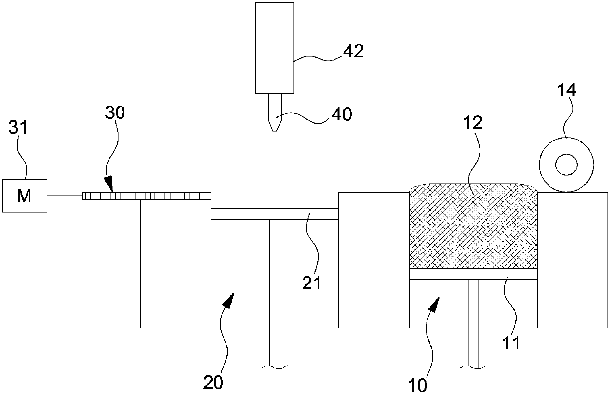
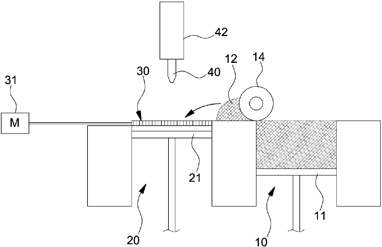
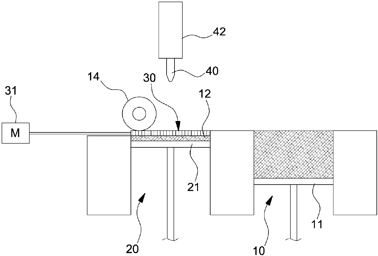
[0050] A normal distribution carbon fiber with an average length of 0.1 mm was prepared in powder form, a mesh with 0.35 mm×0.35 mm voids was prepared, and a work table for lamination molding was set under the mesh.

[0051] Then, the carbon fiber powder with an average length of 0.1 mm passed through the 0.35 mm×0.35 mm gap of the mesh, so that the carbon fiber powder was placed on the table under the mesh at a height of 0.13 mm.

[0052] Then, the urethane acrylate resin (which is a photocurable resin) is printed on the carbon fiber powder placed on the work table in the form of droplets with a size of about 40 μm through a piezoelectric nozzle.

[0053] Subsequently, the urethane acrylate resin printed on the carbon fiber powder was cured by irradiation with ultraviolet rays, and thus the manufacture of the transverse tensile specimen and the longitudinal tensile specimen according to Example 1 was completed.

[0054] In this case, the transverse tensile specimen is made parallel to...

Embodiment 2

[0056] A tensile specimen was manufactured in the same manner as the specimen according to Example 1, except that a glass fiber powder having a normal distribution with an average diameter of 20 μm and an average length of 0.12 mm was prepared.

Embodiment 3

[0058] Tensile specimens were manufactured in the same manner as the specimens according to Example 1, except that the carbon fiber powder was passed through the mesh as in Example 1, and the layer height (the layer height of a lamination) In the step of supplying carbon fiber powder to the table, a 40 kV electric field is applied between the mesh and the table.


PUM

PropertyMeasurementUnit
diameteraaaaaaaaaa
lengthaaaaaaaaaa

Abstract

The present invention relates to an apparatus and a method for manufacturing fiber reinforced plastic products capable of manufacturing fiber reinforced plastic products having excellent longitudinalstrength using a 3D printing method. The fiber reinforced plastic products are molded by using a 3D printing method and after the orientation distribution of reinforced fibers is uniformly distributedin X, Y and Z directions, a photocurable resin is sprayed thereon and impregnated. Accordingly, the device shows excellent mechanical properties with respect to the weight by each X, Y and Z direction.

Description

Technical field [0001] The invention relates to a device and method for manufacturing fiber-reinforced plastic products. More specifically, the present invention relates to an apparatus and method for manufacturing a fiber-reinforced plastic product, which is configured to manufacture a fiber-reinforced plastic product having excellent longitudinal strength by using a 3D printing method. Background technique [0002] Generally, as representative methods for manufacturing fiber-reinforced plastic products, there are injection molding methods and compression molding methods. [0003] In the case of the compression molding method, the length of the reinforcing fiber is completely maintained in the process, so that a sufficient reinforcing effect of the reinforcing fiber can be achieved after molding, but the compression molding method is mainly used to form a sheet with a simple shape Elements, therefore, there are limitations in manufacturing fiber-reinforced plastic products with v...

Claims


Application Information

Patent Timeline
Patent Type & Authority Applications(China)
IPC IPC(8): B29C64/171B29C64/124B29C70/34B33Y30/00
CPCB33Y30/00B29C70/34B33Y70/10B29C70/24B29C64/165B29C64/40B29C70/38B29C2035/0827B29C64/25B29C64/209B29C64/255B29C64/227B29C64/336B29C67/24B33Y10/00B29K2995/0073B29K2995/0077B29K2105/0809B29K2105/14B29K2105/10B29K2105/16
Inventor 崔荣镐崔旼真李喜俊李容范
Owner HYUNDAI MOTOR CO LTD
Why Eureka
Try Eureka