Adjustable mounting frame and unmanned aerial vehicle thereof

A mounting frame and adjustable technology, which is applied in the layout/installation of power units, aircraft parts, transportation and packaging, etc., can solve the problems of low adjustment and positioning efficiency, poor installation and maintenance flexibility, and cumbersome operation, so as to improve the adjustment and positioning efficiency , Improve the flexibility of installation and maintenance, and the effect of convenient operation

Inactive Publication Date: 2018-03-13
珠海佰家科技有限公司
View PDF6 Cites 0 Cited by
  • Summary
  • Abstract
  • Description
  • Claims
  • Application Information

AI Technical Summary

Problems solved by technology

The existing engine adopts a fixed installation method after commissioning, and the engine is directly fixed on the UAV through the fixing frame, and if the engine needs to be adjusted again in the follow-up inspection and maintenance, it is necessary to remove the whole machine and add or remove gaskets and adjust The movement of the engine is used to adjust the matching accuracy and fix it again. The operation is cumbersome, the adjustment and positioning efficiency is low, and the installation and maintenance flexibility is poor.

Method used


Image

  • Adjustable mounting frame and unmanned aerial vehicle thereof
  • Adjustable mounting frame and unmanned aerial vehicle thereof
  • Adjustable mounting frame and unmanned aerial vehicle thereof

Examples


Embodiment 1

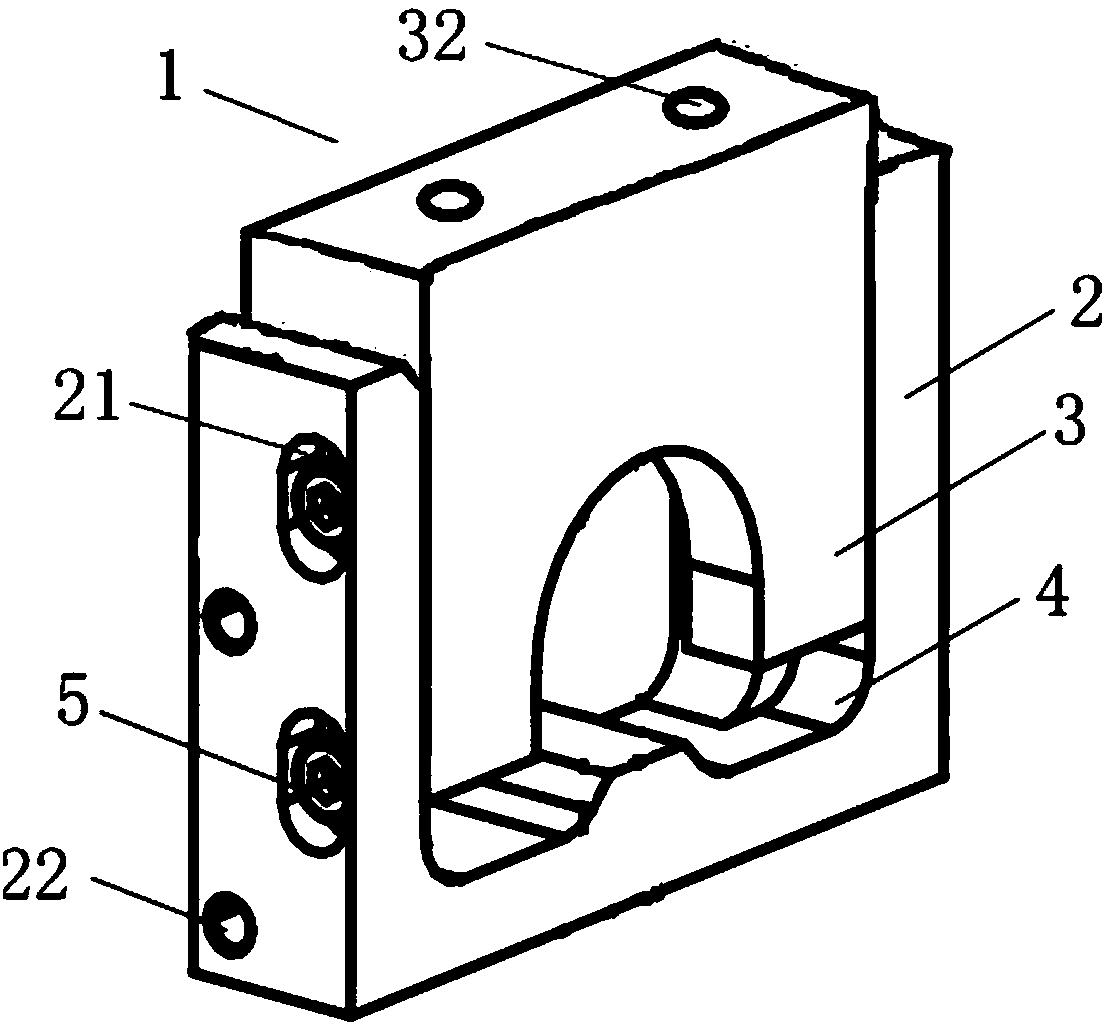
[0032] figure 1 The structural schematic diagram of the adjustable mounting frame 1 provided for the first embodiment of the present invention is shown by figure 1 It can be seen that the adjustable mounting frame 1 provided in this embodiment includes: a fixed support 2, a mounting part 3 and a longitudinal locking mechanism, the fixed support 2 is provided with an accommodating groove 4, and the thickness of the mounting part 3 is smaller than that of the accommodating groove 4 Width, so that the mounting part 3 is adapted to the accommodating groove 4; during installation, the mounting part 3 is placed in the accommodating groove 4, and moves longitudinally along the accommodating groove 4 relative to the fixed support 2; and through the longitudinal locking mechanism Fix the mounting part 3 at any height position in the longitudinal direction of the accommodating groove 4 .

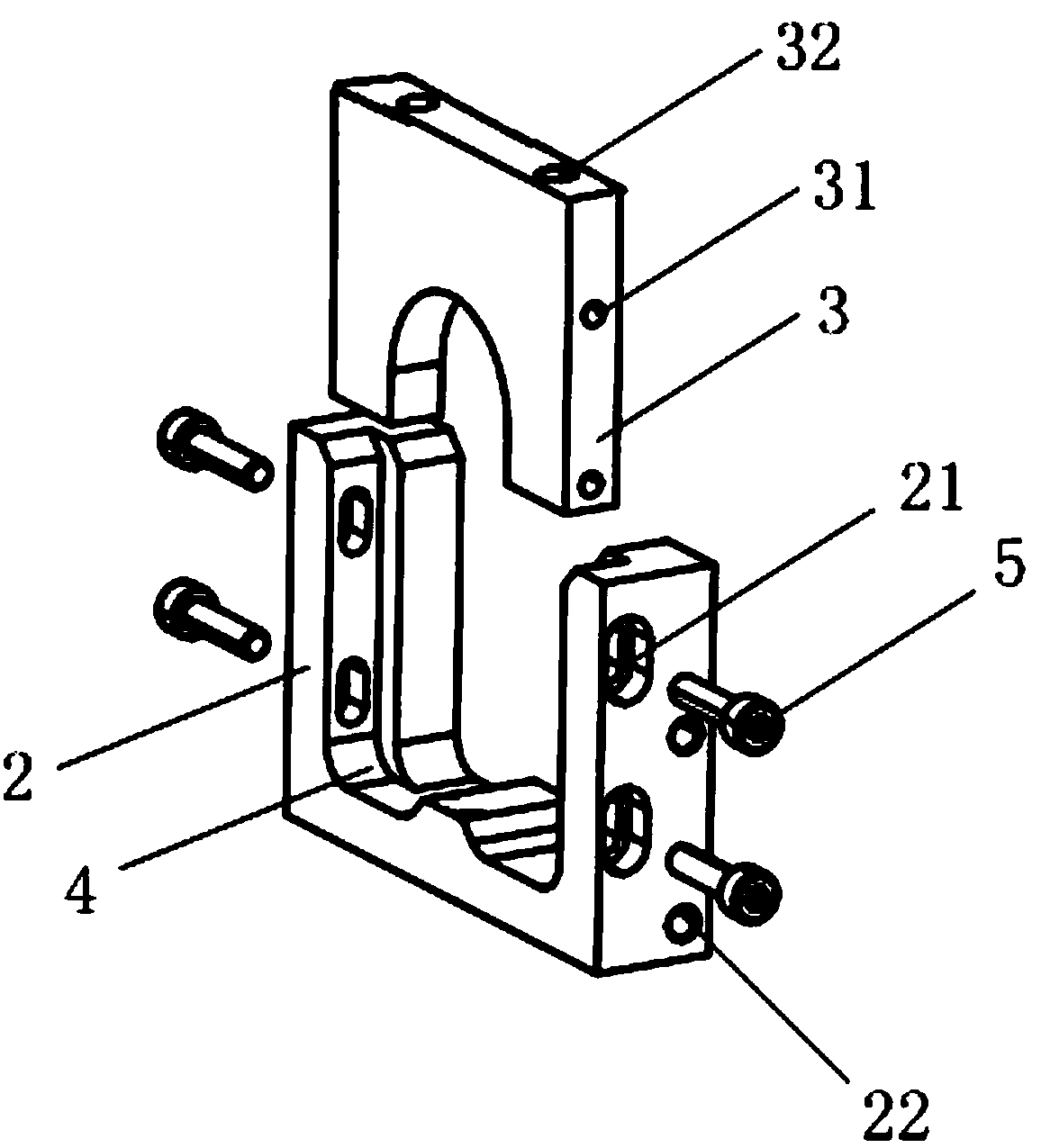
[0033] Specifically as figure 2 As shown, the shape of the accommodating groove 4 in this embod...

Embodiment 2

[0041] Figure 5 The three-dimensional structure schematic diagram of the adjustable mounting frame provided for the second embodiment of the present invention is different from the foregoing embodiments in that, on the basis of the foregoing embodiments, the adjustable mounting frame 1 also includes a function for driving the mounting part 3 in the An elevating adjustment mechanism that moves vertically relative to the fixed support 2 in the accommodating groove 4 . specific as Figure 6 As shown in , the lifting adjustment mechanism in this embodiment includes a second threaded through hole 24 arranged on the bottom edge of the fixed support 2 and a stud 6 matched with the second threaded through hole 24, and the stud 6 can pass through The second threaded through hole 24 enters the accommodation groove 4 and abuts against the mounting part 3. When the stud 6 is screwed in the second threaded through hole 24, the abutting mounting part 3 will be vertically Carry out jackin...


PUM


Abstract

The invention provides an adjustable mounting frame and an unmanned aerial vehicle thereof. The adjustable mounting frame comprises a fixed supporting piece, a mounting piece and a longitudinal locking mechanism, wherein an accommodating groove is formed in the fixed supporting piece; the thickness of the mounting piece is smaller than the width of the accommodating groove, so that the mounting piece is fitted with the accommodating groove; and during mounting, the mounting piece is placed in the accommodating groove, is in longitudinal motion relative to the fixed supporting piece along the accommodating groove, and is fixed to a position at any height in the longitudinal direction of the accommodating groove by the longitudinal locking mechanism. Through the adoption of the adjustable mounting frame disclosed by the invention, when an engine of the unmanned aerial vehicle is mounted, the maneuverability and the mounting and maintaining flexibility can be effectively improved, and thepositioning efficiency can be effectively adjusted.

Description

technical field [0001] The invention relates to the technical field of mounting devices, in particular to an adjustable mounting frame and an unmanned aerial vehicle thereof. Background technique [0002] The engine is the core component of the UAV. The power output of the engine is generally completed by transmitting the torque to each corresponding transmission shaft through a gear set composed of a certain number of gears meshing with each other. When the engine is working, the output shaft outputs power to drive the gear set. Rotating at high speed, the installation and positioning accuracy of the engine affects the working performance of the entire transmission system. [0003] Guarantee the accuracy requirements during the engine assembly process, especially the meshing accuracy between the gear on the engine output shaft and the transmission gear, that is, to ensure the correct contact position between the gears and the appropriate tooth side clearance, so as to furth...

Claims


Application Information

Patent Timeline
Patent Type & Authority Applications(China)
IPC IPC(8): B64D27/26
CPCB64D27/26B64D2027/262
Inventor 贺晓军
Owner 珠海佰家科技有限公司
Why Eureka
Try Eureka