Turbomachine test bench with active noise control

A test bench and turbine technology, which is used in gas turbine engine testing, internal combustion engine testing, and engine testing, etc., can solve problems such as limited efficiency, and achieve the effects of cost reduction, outlet air passage shortening, and row number reduction.

Active Publication Date: 2018-03-13
SAFRAN AERO BOOSTERS SA
View PDF14 Cites 5 Cited by
  • Summary
  • Abstract
  • Description
  • Claims
  • Application Information

AI Technical Summary

Problems solved by technology

However, its efficiency is limited

Method used


Image

  • Turbomachine test bench with active noise control
  • Turbomachine test bench with active noise control
  • Turbomachine test bench with active noise control

Examples


Embodiment Construction

[0050] In the following description, the terms inner and outer refer to an orientation relative to the axis of rotation of the turbomachine. The axial direction corresponds to a direction along the rotational axis of the turbomachine. The radial direction is perpendicular to the axis of rotation. Upstream and downstream refer to the main flow direction in a turbomachine.

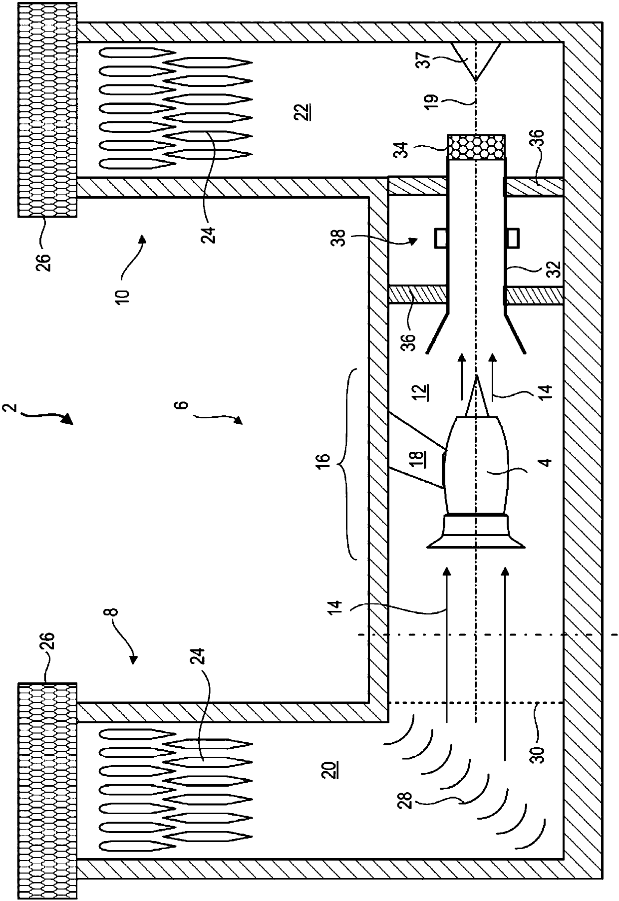
[0051] figure 1 A test rig 2 for an engine 4 is shown in a simplified manner, more specifically a test rig 2 for a turbine 4 , in particular for an aircraft turbojet engine 4 . The test stand 2 can accommodate a complete aircraft, or at least a part of an aircraft.

[0052] The test bench 2 forms the infrastructure, forming a structure. It comprises a channel 6 with an inlet 8 and an outlet 10 . The passageway 6 may comprise a corridor 12 which is substantially long and narrow. Its length may be greater than or equal to 60m. The length of the corridor 12 is such that the airflow 14 flows in a straight...


PUM


Abstract

The invention relates to a test bench for turbomachine comprising: an installation zone for turbomachine; an active system for attenuating the noise emissions produced by the turbomachine. The activesystem includes an attenuation zone with emitters such as loudspeakers; a first microphone placed downstream of the turbomachine; and a second microphone placed downstream of the attenuation zone. Thesystem reduces the turbomachine waves on the basis of the measurements from the first microphone and from the second microphone. The invention also proposes a method for attenuating the noise emissions from the turbomachine tested in the test bench.

Description

technical field [0001] The invention relates to the field of turbomachinery test benches. More precisely, the invention relates to a test stand for a turbojet engine equipped with an active system for attenuating noise emissions inside and outside the test stand. It is a further object of the invention to provide a method for attenuating noise emissions from a turbojet test stand. Background technique [0002] Turbojet engines are tested in specific test rigs during the design, production or maintenance of aircraft. This test rig allows the actual performance of turbojet engines to be tested, while measurements are obtained there. Flow rate, temperature and pressure can be specifically measured there during the actual performance testing phase. Currently, during these practical tests, the turbojet engine emits sound waves in excess of 140dB. However, conventional passive emission mufflers are insufficient at low frequencies where the absorber coating is so high that the ...

Claims


Application Information

Patent Timeline
IPC IPC(8): G01M15/04G01H17/00
CPCG01H17/00G01M15/04F05D2270/333F01D21/003G01M15/14F05D2260/12F05D2270/81G10K11/17857B64F5/60G01M15/02F05D2260/962G10K2210/121F02K1/44F02K1/827B64C1/40B64D2033/0206F01D25/285F02C7/045G10K11/178G10K2210/1281B64F1/26G01M15/12
Inventor B.梅伊斯A.拉克鲁伊科
Owner SAFRAN AERO BOOSTERS SA
Why Eureka
Try Eureka