
Automatic bending machine for machining multiple rows of reinforcing steel bars

A steel bar processing and automatic technology, applied in the field of automatic bending machines for multi-row steel bar processing, can solve the problems of low bending efficiency, troublesome use, and inability to apply steel bar bending operations of different specifications, so as to improve efficiency and use convenient effect

Pending Publication Date: 2018-03-16
泰兴市宏伟机电环保科技有限公司
View PDF0 Cites 2 Cited by
  • Summary
  • Abstract
  • Description
  • Claims
  • Application Information

AI Technical Summary

Benefits of technology

This new design allows an autobender to process many types of metal strips automatically without having to manually adjust them or reposition each strip individually. It also includes a mechanism where the rod holding device holds up one section of wire before being used during another section of work. By placing the rod between two sections of wires instead of directly connecting them together, this technology increases production speed while reducing costs compared to previous methods. Additionally, by allowing the rod holder to hold down more than necessary parts when turning around, the overall weight becomes lighter. Overall, these technical improvements improve the performance and cost effectiveness of automobiles' manufacturing processes.

Problems solved by technology

This patented problem addressed by this newest version of Auto Bender (B) was that current machines were limited because they could only work with single-strength or multi-strand wires for each type of wire used during production. Therefore, there existed limitations when trying to process these types of materials efficiently due to their fixed shape.

Method used


Image

  • Automatic bending machine for machining multiple rows of reinforcing steel bars
  • Automatic bending machine for machining multiple rows of reinforcing steel bars
  • Automatic bending machine for machining multiple rows of reinforcing steel bars

Examples


Embodiment Construction

[0016] The following will clearly and completely describe the technical solutions in the embodiments of the present invention with reference to the accompanying drawings in the embodiments of the present invention. Obviously, the described embodiments are only some of the embodiments of the present invention, not all of them. Based on the embodiments of the present invention, all other embodiments obtained by persons of ordinary skill in the art without making creative efforts belong to the protection scope of the present invention.

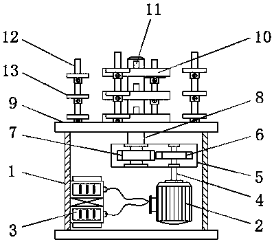
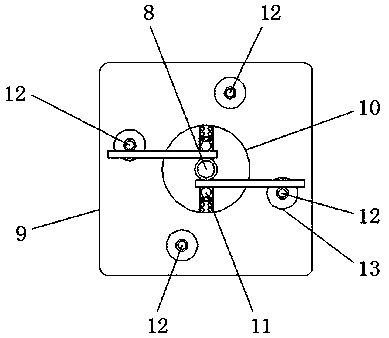
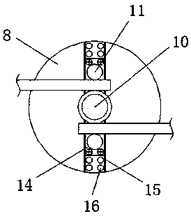
[0017] see Figure 1-3 , the present invention provides a technical solution: an automatic bending machine for processing multiple rows of steel bars, comprising a box body 1, a processing plate 10, a fixed stop bar 12 and a sliding block 14, and a controller 3 is arranged inside the box body 1, And the controller 3 is electrically connected to the motor 2. Since the controller 3 and the motor 2 are commonly used equipment in the automatic bendin...


PUM


Abstract

The invention discloses an automatic bending machine for processing multi-row steel bars, which includes a box body, a processing plate, a fixed stop rod and a sliding block. A controller is arranged inside the box body. The internal input gears are connected to each other, the output gear is connected to the rotating shaft, the processing disc is fixed on the rotating shaft, the lower end of the fixed blocking rod is connected to the box through the workbench, and the fixed blocking rod is fixed with The fixing sleeve is provided with a sliding groove on the processing disc, and the sliding block is fixedly connected with the fixing hole provided in the sliding groove through a fixing piece, and a forming shaft is arranged on the sliding block. The automatic bending machine for multi-row steel bar processing realizes the simultaneous bending of multiple steel bars. The fixed stop bar is a circular distribution structure, and the next bending operation can be performed from different angles without returning to the original position. The forming shaft passes through the The sliding block is fixed in different positions, which is suitable for bending steel bars of different specifications.

Description


Claims


Application Information

Patent Timeline
Owner 泰兴市宏伟机电环保科技有限公司
Learn More