Device for assembling and welding fan casing combined piece

A fan casing and assembly technology, applied in the field of aero-engines, can solve problems such as poor consistency of assembly positioning welding quality, reduced performance of parts, and high labor intensity, and achieve the effects of ingenious structure, weight reduction, and convenient operation

Active Publication Date: 2018-03-16
AECC AVIATION POWER CO LTD
View PDF4 Cites 23 Cited by
  • Summary
  • Abstract
  • Description
  • Claims
  • Application Information

AI Technical Summary

Problems solved by technology

The unevenness of the inner edge plate surface 9 of the blade and the inner flow channel surface 10 of the casing is 0-0.3mm. The assembly positioning welding is guaranteed by manual visual inspection after the operation is completed. Due to the existence of human factors, the quality consistency of the assembly positioning welding is very poor. like figure 2 shown
Moreover, the entire assembly and positioning welding process needs to be completed by more than 2 people. One welding worker is responsible for welding, and another auxiliary worker is needed. It is necessary to insert the blade into the casing window and cooperate with the blade installation edge through the casing window. Experience visual inspection to ensure that the unevenness between the inner edge plate of the blade and the inner runner surface in the casing is 0-0.3mm. It is also necessary to hold the argon protection tube for argon protection during welding. The entire operation process requires two people with very good skills. Tacit cooperation, low efficiency, high labor intensity, greatly reduce the performance of parts, and become the bottleneck link in the production of this part

Method used


Image

  • Device for assembling and welding fan casing combined piece
  • Device for assembling and welding fan casing combined piece
  • Device for assembling and welding fan casing combined piece

Examples


Embodiment Construction

[0045] The present invention will be described in detail below in conjunction with the accompanying drawings and specific embodiments.

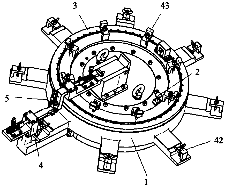
[0046] refer to image 3 , a device for assembling and welding a fan case assembly includes a body assembly 1 , an indexing assembly 2 , a positioning assembly 3 , a pressing assembly 4 and a gas protection assembly 5 .

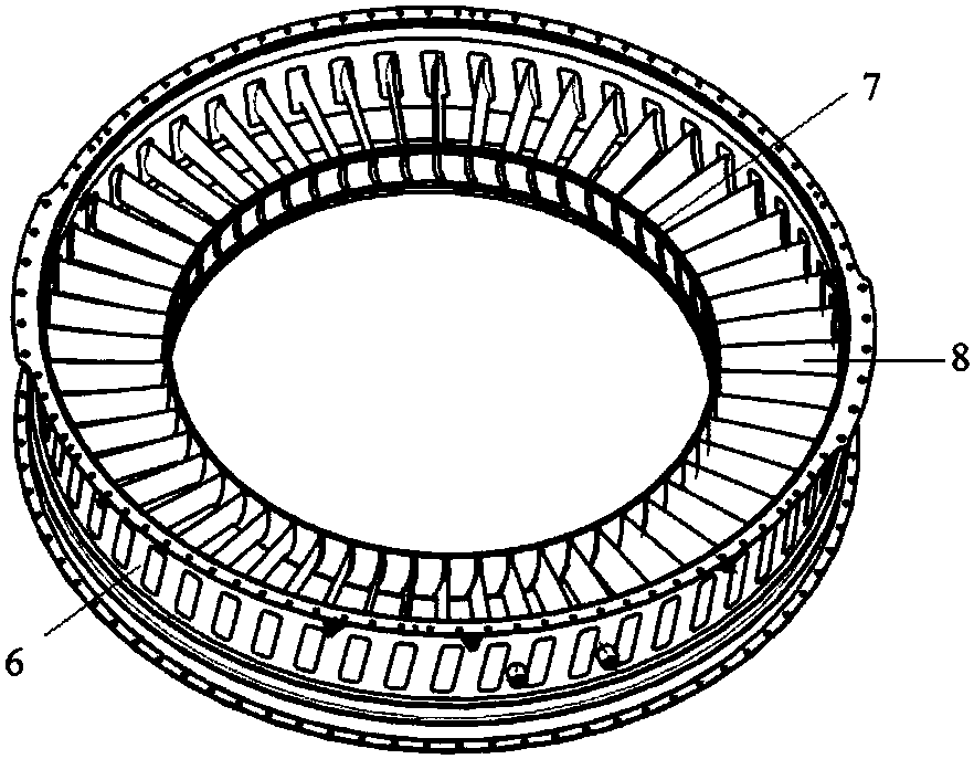
[0047] refer to Figure 4 , the body assembly 1 is a casting structure, including a hollow disc 11, the upper end of the hollow disc 11 is provided with an annular boss 12 concentric with the hollow disc 11, the outer diameter of the annular boss 12 is smaller than the outer diameter of the hollow disc 11, and The inner diameter is larger than the inner diameter of the hollow disc 11, and the outer circumference of the hollow disc 11 is evenly provided with 8 bosses 13 for positioning the center of the casing 6 and combining with the pressing assembly 4 to compress the lower end of the casing. It is a three-step step struc...


PUM


Abstract

The invention discloses a device for assembling and welding a fan casing combined piece. The device comprises a body assembly, a gas protecting assembly and a positioning assembly; the body assembly comprises a hollow disk; a plurality of bosses used for supporting a casing are arranged on the periphery of the hollow disk; the positioning assembly comprises a casing positioning assembly used for positioning the axial direction, the angular direction and the circle center of the casing, an inner ring positioning assembly used for positioning the axial direction, the angular direction and the circle center of an inner ring, a blade boss positioning assembly used for positioning the angular direction of blades, and a blade axial direction positioning assembly; the blade axial direction positioning assembly is arranged on the inner side of the hollow disk, and comprises a hinge plate; one end of the hinge plate is hinged to an overturning base, and the other end of the hinge plate is connected with a positioning block in a sliding manner; a first pressing device is fixedly arranged on the hinge plate; and a pressing head of the first pressing device is fixedly connected with the positioning block. The device is convenient to operate, fast and capable of saving labor, reducing the number of operators, and making blade welding kept consistent.

Description

technical field [0001] The invention belongs to the technical field of aero-engines, and in particular relates to a device for assembling and welding a fan case assembly. Background technique [0002] Such as figure 1 As shown, the aero-engine fan case assembly is composed of a case 6, an inner ring 7 and a full circle of evenly distributed blades 8. With the continuous development of science and technology, new processes and new methods have emerged at the historic moment, and the production speed Faster and faster, the requirements for fan case welding precision are higher and higher, and the welding quality is also continuously improved. The unevenness of the inner edge plate surface 9 of the blade and the inner flow channel surface 10 of the casing is 0-0.3mm. The assembly positioning welding is guaranteed by manual visual inspection after the operation is completed. Due to the existence of human factors, the quality consistency of the assembly positioning welding is ve...

Claims


Application Information

Patent Timeline
Patent Type & Authority Applications(China)
IPC IPC(8): B23K37/04B23K37/00
CPCB23K37/00B23K37/04B23K37/0443
Inventor 党红武王天孔令珊牛阿妮孙洁朱晓婵张占英李涛
Owner AECC AVIATION POWER CO LTD
Why Eureka
Try Eureka