

Rotor for an impact crusher
An impact crusher and rotor technology, applied in grain processing and other directions, can solve the problems of product quality deterioration, prolonged shutdown of the impact crusher, time-consuming replacement of the impact plate, etc., and achieve the effect of reducing the downtime.
- Summary
- Abstract
- Description
- Claims
- Application Information
AI Technical Summary
Problems solved by technology
Method used
Image

Examples
Embodiment Construction
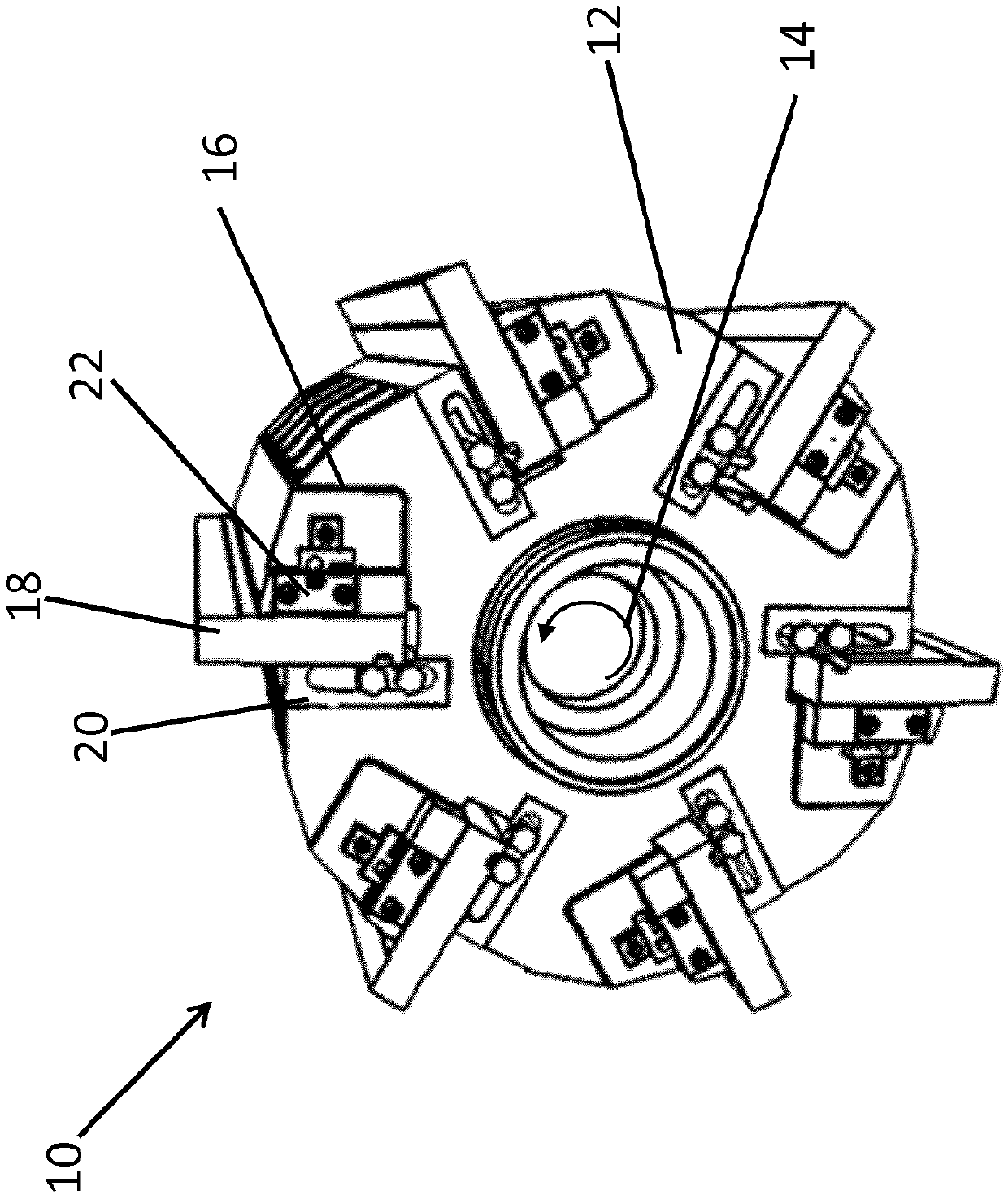
[0036] figure 1 Shown is a rotor 10 of an impact crusher for crushing limestone, marl, clay, crushed stone or similar mineral material. The rotor 10 comprises a generally cylindrical crushing roll body 12 having a central axial bore 14 to receive a shaft (not shown) for driving the crushing roll body. During operation of the impact crusher, the rotor 10 rotates in the direction of the arrow, wherein the striking plate 18, for example, rotates in the opposite direction with another rotor ( figure 1 (not shown) or the striking plate 18 interacts with a striking element (not shown) arranged on the side of the rotor 10 .
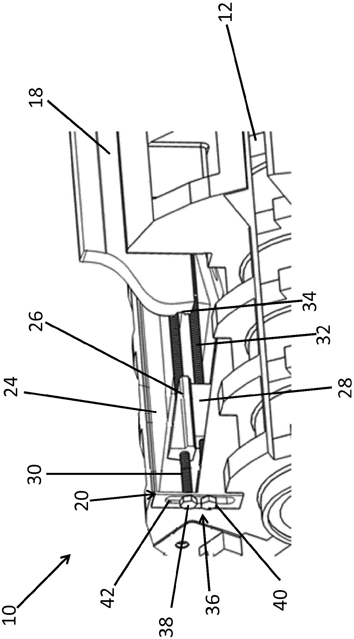
[0037] The crushing roller body 12 has on its outer circumference six recesses 16 extending in the axial direction, and wherein a striking plate 18 and a holding device 20 are arranged in each of the six recesses 16 . The substantially plate-shaped striker plates 18 extend over the entire length of the crushing roll body 12 in the axial direction, so that the ...
PUM
 Abstract
Description
Claims
Application Information