Database deployment method, database deployment device, control equipment and system
A technology for controlling equipment and deploying devices, which is applied in the database field, can solve the problems of time increase and low efficiency of manual configuration, and achieve the effect of improving efficiency and reducing the time used
Active Publication Date: 2018-03-20
TENCENT TECH (SHENZHEN) CO LTD
3 Cites 4 Cited by
AI-Extracted Technical Summary
Problems solved by technology
[0004] Since the process of creating a database requires many steps, manual configuration is very inef...
Method used
[0040] The storage device 40 is used to store database files. For example, the storage device may be a distributed storage system based on Ceph storage technology, and the distributed storage system includes many object storage devices (Object-based Storage Device, OSD for short). Each OSD uses objects (Object) to manage the saved data, and each object is a synthesis of data and data attribute collections. It stores data in the tracks and sectors of the disk, combines several tracks and sectors to form an Object, and provides access to...
Abstract
The invention discloses a database deployment method. The method comprises the steps that control equipment receives a database creating request, wherein the database creating request carries a database framework identity and the database type; according to the database framework identity, a virtual machine is created; according to the database type, database deployment information is determined,and according to the database deployment information, a database is deployed in the virtual machine. The invention further provides a database deployment device which can achieve the database deployment method. By means of the method and the device, time for creating the database can be reduced, and the database deployment efficiency can be improved.
Application Domain
Input/output to record carriersTransmission +2
Technology Topic
Virtual machineControl equipment +3
Image
Examples
- Experimental program(1)
Example Embodiment
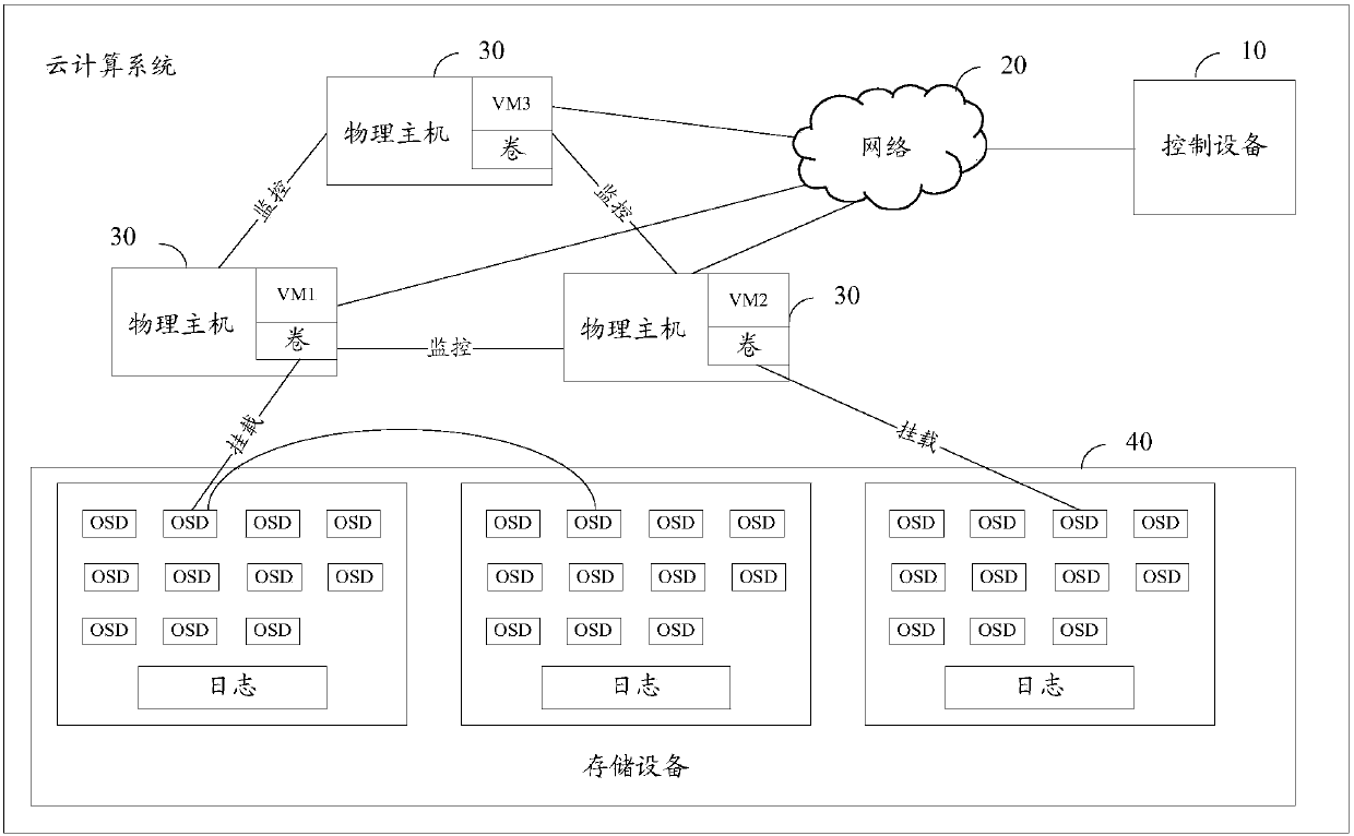
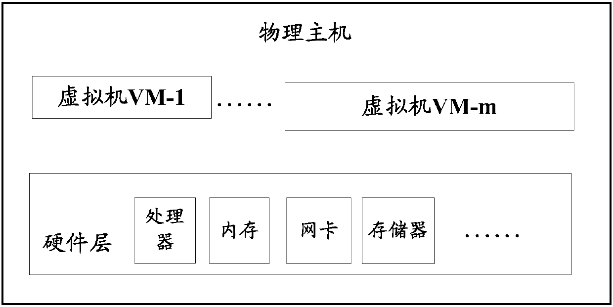
[0031] The database deployment method of the present invention is mainly applied to cloud computing systems. The cloud computing system is described below, please refer to figure 1 , The cloud computing system includes a control device 10, a network 20, multiple physical hosts 30, and a storage device 40.
[0032] The control device 10 is generally implemented by a server. The control device includes an application interface (Application Programming Interface, API for short), a message queue, a scheduler, and other functional components. There can be multiple schedulers and other functional components.
[0033] API: The access module of the control device. All client devices interact with the control device through API components. The API component is responsible for verifying the parameters of the request packet of the virtual machine creation request, routing the request, and distributing it to other components in the system. For asynchronous tasks, the API component will distribute the request packet to the message queue component.
[0034] Message queue: For asynchronous tasks, messages will flow in the message queue. Each component has the identity of a producer or consumer. The producer sends messages to the message queue, and the consumers receive messages from the message queue.
[0035] Scheduler: Used to select a suitable physical host from multiple physical hosts as the host of the virtual machine.
[0036] Other functional components: responsible for virtual machine network management, cloud disk storage management, image management, and virtual machine production.
[0037] The physical host 30 includes a virtual machine and a hardware layer. The hardware layer can provide hardware resources for each virtual machine, such as figure 2 Shown.
[0038] Virtual Machine (VM for short) refers to a complete computer system that has complete hardware system functions and runs in a completely isolated environment that is simulated by software. One or more virtual computers can be simulated by virtual machine software on a physical host, and these virtual machines work like real computers. The operating system and applications can be installed on the virtual machine, and the virtual machine can also Access network resources. For applications running in a virtual machine, the virtual machine is like working in a real computer.
[0039] The hardware layer refers to the hardware platform on which the virtual machine runs. Among them, the hardware layer can include a variety of hardware. For example, the hardware layer of a computing node can include a processor (such as a CPU) and memory, and it can also include high-speed or low-speed input/output (Input/Output, referred to as I/O), such as a network card and memory. ) Devices, and other devices with specific processing functions, such as Input/Output Memory Management Unit (IOMMU), where IOMMU can be used to convert the physical address of the virtual machine and the physical address of the Host.
[0040] The storage device 40 is used to store database files. For example, the storage device may be a distributed storage system based on Ceph storage technology, and the distributed storage system includes many Object-based Storage Devices (OSD for short). Each OSD uses an object (Object) to manage the stored data, and each object is a complex of data and data attribute collections. It stores data in the tracks and sectors of the disk, combines several tracks and sectors to form an Object, and provides access to the data to the outside world through this Object. Each Object is similar to a traditional file and uses the same access interface as the file, including Open, Read, Write, etc. But the two are not the same. Each Object may include several files, or it may be part of a file, and is independent of the operating system. In addition to specific user data, OSD also records the attribute information of each Object, and puts this information on the OSD, which enhances the parallel access performance and scalability of the entire storage system.
[0041] It is understandable that, in the cloud computing system of the present invention, the control device 10 can also be implemented by any physical host 30, and the storage device 40 can also be implemented by adopting the hardware layer of the physical host instead of a distributed design. There is no limitation here.
[0042] Based on the above cloud computing system, the present invention proposes a method for automatically deploying a database on the cloud computing system. For details, please refer to the following embodiments. See image 3 An embodiment of the database deployment method provided by the present invention includes:
[0043] Step 301: The control device receives a database creation request, and the database creation request carries a database architecture identifier and a database type.
[0044] In this embodiment, the user can initiate a database creation request to the control device through the client, and the control device can receive the database creation request. The database creation request carries the database type and the database architecture identifier. The database type may include database version information, such as Structured Query Language (SQL) Server 2008R2.
[0045] Among them, the client refers to a program that provides users with local services, and is generally installed on a user's device, such as a personal computer, mobile phone, tablet computer, or vehicle-mounted computer.
[0046] Step 302: The control device creates a virtual machine in the physical host according to the database architecture identifier.
[0047] Specifically, the database architecture identification includes a highly available database identification and a stand-alone architecture identification.
[0048] If the database architecture identifier is a highly available database architecture identifier, the control device can create multiple virtual machines. Among the multiple virtual machines, there are at least one primary virtual machine for undertaking business load, at least one secondary virtual machine for undertaking business load when the primary virtual machine fails, and at least one monitoring virtual machine. The machine is used to monitor the main virtual machine and the auxiliary virtual machine, and perform the arbitration function of automatic switching. It should be noted that the primary virtual machine, secondary virtual machine, and monitoring virtual machine are created on different physical hosts.
[0049] If the database architecture identifier is a single-machine architecture identifier, the control device can create a virtual machine for undertaking business load on a physical host. The number of the virtual machine may be one or multiple, which is not limited here.
[0050] Step 303: The control device determines database configuration information according to the database type.
[0051] After the control device receives the database creation request, the control device determines the database configuration information corresponding to the database type from the preset database configuration information. The database type can be MySQL or MS SQL Server, or Oracle, DB2, Sybase, or other types of databases, and there is no limitation here.
[0052] For example, if the database type requested by the user is MS SQL Server, the control device determines that the database configuration information is MS SQL Server database configuration information. If the database type is MySQL, the control device determines that the database configuration information is MySQL database configuration information.
[0053] It should be noted that there is no fixed order for step 303 and step 302, and the specific execution order is not limited here.
[0054] Step 304: The control device deploys the database in the virtual machine according to the database configuration information.
[0055] After the control device determines the database configuration information, the database configuration information can be used to deploy the database in the virtual machine. After the deployment is complete, users can access and use the database on the virtual machine.
[0056] In this embodiment, the control device can automatically create a virtual machine, and can also select database configuration information according to the database type, and then automatically configure the database on the virtual machine according to the database configuration information. It can be seen that this embodiment can automatically create a database in the cloud computing system without manual intervention. Compared with manually creating a database, this embodiment can shorten the time for creating a database and improve the efficiency of creating a database. Especially when processing a large number of database creation requests, the efficiency of creating a database can be greatly improved.
[0057] Divided by the reliability of the database, the database architecture can be divided into a highly available database architecture and a stand-alone architecture. The following is an introduction to the automatic deployment process of databases of different architectures. First, the automatic deployment process of a stand-alone database is explained in detail:
[0058] Step 401: The control device receives a database creation request, and the database creation request carries a stand-alone architecture identifier and a database type.
[0059] In this embodiment, the user can send a database creation request to the control device through the client, and the database architecture identifier carried in the database creation request is the stand-alone architecture identifier. Database type can refer to image 3 , I won’t repeat it here.
[0060] It should be noted that in practical applications, the default architecture of the database may be a stand-alone architecture. When the database creation request does not carry the high-availability database architecture identifier, it indicates that the applied database is a stand-alone database, and the control device may execute step 402.
[0061] Step 402: The control device creates a virtual machine according to preset virtual machine configuration information.
[0062] After the control device determines that the database architecture is a single-machine architecture, it can select a physical host from the standby physical hosts, and then install the virtual machine's operating system and set the virtual machine network type on the physical host according to the virtual machine configuration information. The virtual machine configuration information includes volume configuration information, and the volume configuration information is used to mount storage volumes for the virtual machine.
[0063] The virtual machine configuration information is preset and controlled by the service provider in the device or the physical host. Virtual machine configuration information includes at least but not limited to the following information: number of processors, number of processor cores, virtual machine memory capacity, operating system, network type, I/O controller type, disk type, virtual disk capacity, virtual disk partition information , The disk name of the virtual disk, etc.
[0064] Step 403: The control device creates a storage volume according to the volume configuration information, and mounts the storage volume to the virtual machine.
[0065] The control device may create a storage volume according to the volume configuration information in the virtual machine configuration information, and then mount the storage volume on the virtual machine to store the database file. One storage volume can be implemented by multiple OSDs, that is, when the storage volume stores files, the files can be stored in multiple OSDs respectively.
[0066] Step 404: The control device initializes the virtual machine.
[0067] The virtual machine needs to be initialized before it can be accessed by users. The virtual machine initialization process is as follows:
[0068] The control device may generate an Internet Protocol (Internet Protocol, IP for short) address and use it as the IP address of the virtual machine. The specific method for the control device to generate the IP address may be: selecting any IP address from the IP addresses to be allocated. The IP address to be allocated refers to an IP address other than the allocated IP address in the accessible network. The accessible network generally refers to the corporate LAN.
[0069] The control device can also generate a virtual machine name, and name the virtual machine with the virtual machine name. For example, the naming rule may be: computer room location + database type + virtual machine serial number + ‘-’ + virtual machine number. For example, TJMSSQL000002-1. It is understandable that the naming rules are not limited to the above examples, and other naming methods can also be used, which are not limited here.
[0070] Step 405: The control device determines database configuration information according to the database type.
[0071] It can be understood that step 405 is similar to step 303, and will not be repeated here.
[0072] Step 406: The control device deploys the database in the virtual machine according to the database configuration information.
[0073] After the control device determines the database configuration information, it can establish a database in the virtual machine, and initialize the database according to the database configuration information. After the configuration is successful, the user can access and use the database.
[0074] This embodiment can automatically create a database in the cloud computing system without manual intervention. Compared with manually creating a database, this embodiment can shorten the time for creating a database and improve the efficiency of creating a database.
[0075] Secondly, this embodiment describes in detail the process of automatically creating a virtual machine and the process of automatically configuring a database in the virtual machine.
[0076] based on Figure 4 In the illustrated embodiment, in an optional embodiment of the present invention, after step 405 and before step 406, the foregoing database deployment method further includes:
[0077] The control device sets the domain name of the virtual machine and adds the virtual machine to the accessible network.
[0078] In this embodiment, the accessible network generally refers to an enterprise local area network. After the control device sets the domain name for the virtual machine, restart the virtual machine to add the virtual machine to the accessible network. After the virtual machine enters the domain, the user can directly access the virtual machine by entering the domain name on the client.
[0079] The above has introduced the automatic deployment process of the database of the stand-alone architecture, and the automatic deployment process of the database of the highly available database architecture is described in detail below. See Figure 5 Another embodiment of the database deployment method provided by the present invention includes:
[0080] Step 501: The control device receives a database creation request, and the data creation request includes the high-availability database architecture identifier and the database type.
[0081] In this embodiment, the user may send a database creation request to the control device through the client, and the database architecture identifier carried in the database creation request is a highly available database architecture identifier. Database type can refer to image 3 Example shown.
[0082] Step 502: The control device creates a primary virtual machine and an auxiliary virtual machine according to the first preset virtual machine configuration information, and creates a monitoring virtual machine according to the second preset virtual machine configuration information.
[0083] Wherein, the first preset virtual machine configuration information includes virtual machine configuration information and volume configuration information. The volume configuration information is used to mount storage volumes for the virtual machine. The second preset virtual machine configuration information includes virtual machine configuration information and may not include Volume configuration information.
[0084] The control device can select a physical host from the standby physical hosts, and then create a primary virtual machine on the physical host according to the virtual machine configuration information. The process of creating a secondary virtual machine by the control device is similar to that of the primary virtual machine. The primary virtual machine is used to bear the business load, and the auxiliary virtual machine is used to bear the business load when the primary virtual machine fails.
[0085] The control device selects another physical host, and creates a monitoring virtual machine based on the virtual machine configuration information. The monitoring virtual machine does not bear the business load, and is used for fault detection and the arbitration function of automatic switching.
[0086] It should be noted that the primary virtual machine, the secondary virtual machine, and the monitoring virtual machine are respectively set on different physical hosts. The above three nodes can check the status of each other through the network. The primary virtual machine and the secondary virtual machine have equal roles and can exchange roles.
[0087] Step 503: The control device creates a first storage volume and a second storage volume according to the volume configuration information, mounts the first storage volume on the primary virtual machine, and mounts the second storage volume on the secondary virtual machine.
[0088] After the control device initializes the primary virtual machine and the secondary virtual machine, it can create the first storage volume and the second storage volume respectively according to the volume configuration information, mount the first storage volume on the primary virtual machine, and mount the second storage volume Loaded in the auxiliary virtual machine. Then, the control device may call a volume initialization (initVolume) script to initialize the first storage volume and the second storage volume respectively. It is understandable that since the primary virtual machine and the secondary virtual machine have to bear the business load, storage volumes need to be mounted, while the monitoring virtual machine does not need to bear the business load, so storage resources may not be mounted.
[0089] Step 504: The control device initializes the primary virtual machine, the secondary virtual machine, and the monitoring virtual machine respectively.
[0090] Wherein, step 504 may specifically be: the control device generates a first virtual machine name and a first IP address, uses the first virtual machine name as the virtual machine name of the main virtual machine, and uses the first IP address as the IP address of the main virtual machine; The control device generates the second virtual machine name and the second IP address, uses the second virtual machine name as the virtual machine name of the auxiliary virtual machine, and uses the second IP address as the IP address of the auxiliary virtual machine; the control device generates the third virtual machine name And the third IP address, using the third virtual machine name as the virtual machine name of the monitoring virtual machine, and using the third IP address as the IP address of the monitoring virtual machine.
[0091] For example, the virtual machine name and IP address settings can be as shown in the following table:
[0092]
[0093] Step 505: The control device determines database configuration information according to the database type.
[0094] It can be understood that step 505 is similar to step 303 and will not be repeated here.
[0095] Step 506: The control device establishes a first database in the primary virtual machine, and initializes the first database according to the database configuration information; establishes a second database in the auxiliary virtual machine, and configures the second database as the first database according to the database configuration information Mirrored database.
[0096] The control device establishes a database in the main virtual machine and the auxiliary virtual machine respectively, and initializes the database respectively. The control device configures the database schemes in the primary virtual machine and the secondary virtual machine as mirrors, so that when the primary virtual machine fails, the cloud computing system can switch to the secondary virtual machine, and the secondary virtual machine processes services. At this time, the user does not need to be aware of the failure of the main virtual machine, and for the user, the cloud computing system can still operate normally.
[0097] Due to the complexity of highly available databases, it takes a lot of time to manually create highly available databases. This embodiment can automatically create a highly available database in the cloud computing system without manual intervention. It can be seen that this embodiment can greatly shorten the time for creating a database and improve the efficiency of creating a database.
[0098] Secondly, this embodiment describes in detail the process of automatically creating multiple virtual machines and the process of automatically configuring highly available databases in multiple virtual machines. Therefore, this embodiment has good feasibility.
[0099] based on Figure 5 In the illustrated embodiment, in an optional embodiment of the present invention, after step 505 and before step 506, the foregoing database deployment method further includes:
[0100] The control device respectively sets the domain name of the main virtual machine, the domain name of the auxiliary virtual machine, and the domain name of the monitoring virtual machine, and adds the main virtual machine, the auxiliary virtual machine, and the monitoring virtual machine to the accessible network.
[0101] In this embodiment, the accessible network generally refers to an enterprise local area network. After the control device sets the domain names for the primary virtual machine, secondary virtual machine, and monitoring virtual machine, the virtual machine needs to be restarted to add the above virtual machines to the accessible network. After the above virtual machine enters the domain, the user can directly access the corresponding virtual machine by entering the domain name on the client.
[0102] It should be noted that if an exception occurs during the deployment of the database in the cloud computing system and the creation fails, the control device can roll back the virtual machine and the volume, and record the generated exception information in the log.
[0103] For ease of understanding, the following takes the creation of a SQL Server 2008R2 database on a cloud computing system as an example for detailed introduction. In the specific application scenario of the present invention, the storage device is an object storage system.
[0104] The user initiates a database creation request to the control device, and the control device determines whether the database type is SQLServer 2008R2. If it is, it determines whether the database architecture is a highly available database architecture. If so, executes the high-availability database creation process, such as Image 6 As shown, if not, execute the database creation process of the stand-alone architecture, such as Figure 7 Shown.
[0105] See Image 6 , The high-availability database creation process is as follows:
[0106] The control device selects host A, host B, and host C from alternate hosts; creates VM1 and storage volume 1 on host A according to the virtual machine configuration information, mounts storage volume 1 on VM1; creates VM2 and storage volume on host B 2. Mount storage volume 2 on VM2; create VM3 on host C.
[0107] Set the IP of VM1 to 169.254.169.11, name VM1 to SZSQL-1; set the IP of VM2 to 169.254.169.12, name VM2 to SZSQL-2; set the IP of VM3 to 169.254.169.13, and name VM3 to SZSQL-3.
[0108] If it is SZSQL-1, the control device will initialize storage volume 1 and set storage volume 1 as drive D; if it is SZSQL-2, it will initialize storage volume 2 and set storage volume 2 as drive D.
[0109] The control device sets up domain names for host A, host B, and host C respectively, and adds host A, host B, and host C to the enterprise LAN. After successfully entering the domain, enterprise users can access the corresponding host through the domain name.
[0110] The control device configures the SQL Server 2008R2 database on the host A and the host B respectively, and sets the database mode to a highly available architecture. After the configuration is completed, the host A and the host B can respectively send a database deployment completion message to the control device, for example, 200, 200 indicates that the database deployment is successful. During the database creation process, if an exception occurs during the creation process, the server rolls back the virtual machine and volume, and writes an error report to the log.
[0111] See Figure 7 , The creation process of executing a stand-alone database is as follows:
[0112] The control device selects host D from the standby host; creates VM0 and storage volume 3 on host D according to the virtual machine configuration information, and mounts storage volume 3 on VM0; set the IP address of virtual machine SZSQL-0 to 169.254.169.10, VM0 is named SZ-SQL0; the storage volume 3 is initialized; the domain name of the virtual machine SZSQL-0 is set; the SQLServer 2008 database is established on the virtual machine SZSQL-0, and the SQL configuration is performed according to the database configuration information.
[0113] The database deployment method provided by the present invention is described in detail above from the perspective of the method, and the database deployment device provided by the present invention is introduced from the device perspective below:
[0114] See Figure 8 An embodiment of the database deployment device 800 provided by the present invention includes:
[0115] The interface module 801 is configured to receive a database creation request, and the database creation request carries a database architecture identifier and a database type;
[0116] The virtual machine creation module 802 is used to create a virtual machine according to the database architecture identifier, and the virtual machine is set in the physical host;
[0117] The determining module 803 is used to determine database configuration information according to the database type;
[0118] The database deployment module 804 is used to deploy the database in the virtual machine according to the database configuration information.
[0119] See Picture 9 In an optional embodiment of the present invention, the cloud computing system further includes a storage device;
[0120] The virtual machine creation module 802 includes:
[0121] The first creating unit 901 is configured to, if the database architecture identifier is a high-availability database architecture identifier, create a primary virtual machine and an auxiliary virtual machine according to the first preset virtual machine configuration information, and create a monitor according to the second preset virtual machine configuration information A virtual machine, where the first preset virtual machine configuration information includes volume configuration information, and the primary virtual machine, the secondary virtual machine, and the monitoring virtual machine are set in different physical hosts;
[0122] The first mounting unit 902 is configured to create a first storage volume according to the volume configuration information, and mount the first storage volume to the primary virtual machine;
[0123] The second mounting unit 903 is configured to create a second storage volume according to the volume configuration information, and mount the second storage volume to the secondary virtual machine;
[0124] The first setting unit 904 is used to initialize the main virtual machine, the auxiliary virtual machine and the monitoring virtual machine respectively.
[0125] Further, in another optional embodiment of the present invention, the creating database module 804 includes:
[0126] The first establishing unit 905 is configured to establish a first database in the main virtual machine;
[0127] The first configuration unit 906 is configured to initialize and configure the first database according to the database configuration information;
[0128] The second establishing unit 907 is configured to establish a second database in the auxiliary virtual machine;
[0129] The second configuration unit 908 is configured to configure the second database as a mirror database of the first database according to the database configuration information.
[0130] See Picture 10 In another optional embodiment of the present invention, the first setting unit 904 includes:
[0131] The first setting subunit 1001 is configured to generate a first virtual machine name and a first IP address, use the first virtual machine name as the virtual machine name of the main virtual machine, and use the first IP address as the IP address of the main virtual machine;
[0132] The second setting subunit 1002 is configured to generate a second virtual machine name and a second IP address, use the second virtual machine name as the virtual machine name of the secondary virtual machine, and use the second IP address as the IP address of the secondary virtual machine;
[0133] The third setting subunit 1003 is used for generating a third virtual machine name and a third IP address, using the third virtual machine name as the virtual machine name of the monitoring virtual machine, and using the third IP address as the IP address of the monitoring virtual machine.
[0134] Further, in another optional embodiment of the present invention, the virtual machine creation module 802 further includes:
[0135] The second setting unit 1101 is also used to set the domain name of the main virtual machine, the domain name of the auxiliary virtual machine, and the domain name of the monitoring virtual machine respectively, and add the main virtual machine, the auxiliary virtual machine, and the monitoring virtual machine to the accessible network.
[0136] See Picture 12 In another optional embodiment of the present invention, the cloud computing system further includes a storage device; the virtual machine creation module 802 includes:
[0137] The second creation unit 1201 is configured to create a virtual machine according to preset virtual machine configuration information if the database architecture identifier is a single-machine architecture identifier, and the virtual machine configuration information includes volume configuration information;
[0138] The third mounting unit 1202 is configured to create a storage volume according to the volume configuration information, and mount the storage volume to the virtual machine;
[0139] The third setting unit 1203 is used to initialize the virtual machine.
[0140] Further, in another optional embodiment of the present invention, deploying the database module 804 includes:
[0141] The third establishment unit 1204 is used to establish a database in the virtual machine;
[0142] The third configuration unit 1205 is used to initialize the database according to the database configuration information.
[0143] Further, in another alternative embodiment of the present invention, although Picture 12 Not shown, creating a virtual machine module may also include:
[0144] The fourth setting unit is used to set the domain name of the virtual machine and add the virtual machine to the accessible network.
[0145] For ease of understanding, the following uses a specific application scenario to describe in detail the interaction between the modules in the database deployment apparatus provided by the embodiment of the present invention:
[0146] The user initiates a database creation request to the server, and the receiving module 801 determines whether the database type is SQL Server 2008 R2, and if so, determines that the database configuration information is SQL Server 2008 R2 database configuration information.
[0147] The receiving module 801 judges whether the database architecture is a high-availability database architecture. If so, the virtual machine module 802 and the deployment database module 804 execute the high-availability database creation process; if not, the virtual machine module 802 and the deployment database module 804 execute the stand-alone architecture The database creation process.
[0148] The high-availability database creation process is as follows:
[0149] The first creation unit 901 selects host A, host B, and host C from the standby hosts. The first creation unit 901 creates VM1 on host A according to the virtual machine configuration information, the first mounting unit 902 creates storage volume 1 according to the volume configuration information, mounts the storage volume 1 on VM1; creates VM2 on host B, and the second The mounting unit 903 creates storage volume 2 according to the volume configuration information, mounts the storage volume 2 to VM2; creates VM3 on host C.
[0150] The first setting unit 904 initializes the main virtual machine, the auxiliary virtual machine, and the monitoring virtual machine. The specific process is as follows: the first setting subunit 1001 sets the IP of VM1 to 169.254.169.11, and names VM1 as SZSQL-1; The second setting subunit 1002 sets the IP of VM2 to 169.254.169.12, and names VM2 as SZSQL-2; the third setting subunit 1003 sets the IP of VM3 to 169.254.169.13, and names VM3 as SZSQL-3.
[0151] If it is SZSQL-1, the first setting unit 904 initializes storage volume 1 and sets storage volume 1 to drive D; if it is SZSQL-2, the first setting unit 904 initializes storage volume 2 and sets storage volume 2 to D Drive letter.
[0152] The second setting subunit 1101 sets domain names for the host A, the host B, and the host C respectively, and adds the host A, the host B, and the host C to the enterprise LAN. After successfully entering the domain, enterprise users can access the corresponding host through the domain name.
[0153] The first establishment unit 905 establishes the database of SQL Server 2008R2 on host A, the first configuration unit 906 initializes and configures the database according to the database configuration information, the second establishment unit 907 establishes the database of SQL Server 2008R2 on host B, and the second configuration The unit sets the database of host B as a mirror database of the database of host A according to the database configuration information. After the configuration is completed, host A can send a database deployment complete message to the server, for example, 200, 200 indicates that the database deployment is successful. During the database creation process, if an exception occurs during the creation process, the server rolls back the virtual machine and volume, and writes an error report to the log.
[0154] The process of creating a stand-alone database is as follows:
[0155] The second creation unit 1201 selects host D from the alternate hosts; creates VM0 on the host D according to the virtual machine configuration information, and the third mounting unit 1203 creates storage volume 3, and mounts the storage volume 3 on VM0; third setting unit 1202 Set the IP address of the virtual machine VM0 to 169.254.169.10, name VM0 as SZ-SQL0, and initialize storage volume 3; the fourth setting unit sets the domain name of the virtual machine SZSQL-0; the third setting unit 1204 is in the virtual machine SZSQL-0 The SQL Server 2008R2 database is established on the upper, and the third configuration unit 1205 performs SQL configuration according to the database configuration information.
[0156] The foregoing describes the database deployment device in the embodiment of the present invention from the perspective of functional modules. The following describes the database deployment device in the embodiment of the present invention from the hardware perspective:
[0157] See Figure 13 , An embodiment of the present invention provides a server 1300, which can implement Figure 3 to Figure 7 The function of the control device in the illustrated embodiment. The control device can include multiple units such as Figure 8 ~ Figure 12 The database deployment device shown. The server 1300 includes:
[0158] An input device 1301, an output device 1302, at least one processor 1303, and at least one memory 1304 connected to each other by a bus; wherein, the memory 1304 may be short-term storage or persistent storage. The program stored in the memory 1304 may include one or more modules, and each module may include a series of instruction operations on the server. Furthermore, the central processing unit 1303 may be configured to communicate with the memory 1304, and execute a series of instruction operations in the memory 1304 on the server 1300.
[0159] The server 1300 may also include one or more power supplies, one or more wired or wireless network interfaces, one or more input and output interfaces, and/or one or more operating systems, such as WindowsServerTM, Mac OS XTM, UnixTM, LinuxTM , FreeBSDTM and so on. The steps performed by the server in the above embodiment can be based on the Figure 13 The server structure shown.
[0160] By calling the operation instructions stored in the memory 1304, the processor 1303 is used to execute the following methods:
[0161] Receive a database creation request, the database creation request carries the database architecture identifier and database type;
[0162] Create a virtual machine according to the database architecture identifier, and the virtual machine is set in the physical host;
[0163] Determine the database configuration information according to the database type, and deploy the database in the virtual machine according to the database configuration information.
[0164] In some embodiments of the present invention, the processor 1303 is specifically configured to create the primary virtual machine and the secondary virtual machine according to the first preset virtual machine configuration information if the database architecture is identified as the high-availability database architecture identification, and according to the second preset Set virtual machine configuration information to create a monitoring virtual machine, where the first preset virtual machine configuration information includes volume configuration information, and the primary virtual machine, the secondary virtual machine, and the monitoring virtual machine are set in different physical hosts;
[0165] Create a first storage volume and a second storage volume according to the volume configuration information, mount the first storage volume to the primary virtual machine, and mount the second storage volume to the secondary virtual machine;
[0166] Initialize the primary virtual machine, secondary virtual machine, and monitoring virtual machine respectively.
[0167] In some embodiments of the present invention, the processor 1303 is specifically configured to establish a first database in the main virtual machine, and initialize and configure the first database according to database configuration information;
[0168] A second database is established in the auxiliary virtual machine, and the second database is configured as a mirror database of the first database according to the database configuration information.
[0169] In some embodiments of the present invention, the processor 1303 is specifically configured to generate a first virtual machine name and a first IP address, use the first virtual machine name as the virtual machine name of the primary virtual machine, and use the first IP address as the primary virtual machine name. The IP address of the machine;
[0170] Generating a second virtual machine name and a second IP address, using the second virtual machine name as the virtual machine name of the auxiliary virtual machine, and using the second IP address as the IP address of the auxiliary virtual machine;
[0171] A third virtual machine name and a third IP address are generated, the third virtual machine name is used as the virtual machine name of the monitoring virtual machine, and the third IP address is used as the IP address of the monitoring virtual machine.
[0172] In some embodiments of the present invention, the processor 1303 is specifically configured to respectively set the domain name of the main virtual machine, the domain name of the auxiliary virtual machine, and the domain name of the monitoring virtual machine; add the main virtual machine, the auxiliary virtual machine, and the monitoring virtual machine to be accessible The internet.
[0173] In some embodiments of the present invention, the processor 1303 is specifically configured to create a virtual machine according to preset virtual machine configuration information if the database architecture identifier is a stand-alone architecture identifier. The preset virtual machine configuration information includes volume configuration information; according to the volume configuration information Create a storage volume, mount the storage volume on the virtual machine; initialize the virtual machine.
[0174] In some embodiments of the present invention, the processor 1303 is specifically configured to establish a database in the virtual machine, and initialize the database according to the database configuration information.
[0175] The embodiment of the present invention also provides a cloud computing system, including:
[0176] Such as Figure 13 The control device shown in the illustrated embodiment or alternative embodiment, and multiple physical hosts.
[0177] In the several embodiments provided by the present invention, it should be understood that the disclosed system, device, and method may be implemented in other ways. For example, the device embodiments described above are merely illustrative. For example, the division of the above-mentioned units is only a logical function division, and there may be other divisions in actual implementation, for example, multiple units or components may be combined or may be Integrate into another system, or some features can be ignored or not implemented. In addition, the displayed or discussed mutual coupling or direct coupling or communication connection may be indirect coupling or communication connection through some interfaces, devices or units, and may be in electrical, mechanical or other forms.
[0178] The units described above as separate components may or may not be physically separated, and the components displayed as units may or may not be physical units, that is, they may be located in one place, or they may be distributed on multiple network units. Some or all of the units may be selected according to actual needs to achieve the objectives of the solutions of the embodiments.
[0179] In addition, the functional units in each embodiment of the present invention may be integrated into one processing unit, or each unit may exist alone physically, or two or more units may be integrated into one unit. The above-mentioned integrated unit can be realized in the form of hardware or software functional unit.
[0180] If the above-mentioned integrated unit is implemented in the form of a software functional unit and sold or used as an independent product, it can be stored in a computer readable storage medium. Based on this understanding, the technical solution of the present invention essentially or the part that contributes to the prior art or all or part of the technical solution can be embodied in the form of a software product, and the computer software product is stored in a storage medium , Including several instructions to make a computer device (which may be a personal computer, a server, or a network device, etc.) execute all or part of the steps of the above methods of the various embodiments of the present invention. The aforementioned storage media include: U disk, mobile hard disk, read-only memory (Read-Only Memory, ROM for short), random access memory (Random Access Memory, RAM for short), magnetic disks or optical disks, etc., which can store program code Medium.
[0181] The above embodiments are only used to illustrate the technical solutions of the present invention, not to limit them; although the present invention has been described in detail with reference to the foregoing embodiments, a person of ordinary skill in the art should understand that: The recorded technical solutions are modified, or some of the technical features are equivalently replaced; these modifications or replacements do not cause the essence of the corresponding technical solutions to deviate from the scope of the technical solutions of the embodiments of the present invention.
PUM


Description & Claims & Application Information
We can also present the details of the Description, Claims and Application information to help users get a comprehensive understanding of the technical details of the patent, such as background art, summary of invention, brief description of drawings, description of embodiments, and other original content. On the other hand, users can also determine the specific scope of protection of the technology through the list of claims; as well as understand the changes in the life cycle of the technology with the presentation of the patent timeline. Login to view more.
Similar technology patents
Quick loading and unloading construct for heavy construct and manufacturing method thereof
ActiveCN111908377Areduce time spentFacilitates fast and precise installation
Owner:CCCC WUHAN HARBOR ENG DESIGN & RES
Method for building scaffold device in hyperboloid linear cabin
InactiveCN107444582Areduce time spentbuild fast
Owner:GUANGZHOU SHIPYARD INTERNATIONAL LTD
Index file generation method, apparatus and system
ActiveCN107179953Aincrease generation speedreduce time spent
Owner:BEIJING QIYI CENTURY SCI & TECH CO LTD
Leg rehabilitation bed
Owner:DONGGUAN BEIYANG IND DESIGN CO LTD
Storage device and data writing method
PendingCN111986721Areduce time spent
Owner:HUAWEI TECH CO LTD +1
Classification and recommendation of technical efficacy words
- reduce time spent
- Improve efficiency
Hydraulic control system and apparatus for split positioning of ship body
ActiveCN101318538AIncrease collapse speedreduce time spent
Owner:ZHONGCHUAN NO 9 DESIGN & RES INST
Method for molding composite material wind power blade root
Owner:LUOYANG SUNRUI WIND TURBINE BLADE
Data storage method and device and storage system
Owner:HUAWEI TECH CO LTD
Method for establishing control channel in cognitive radio network
Owner:HOHAI UNIV CHANGZHOU
Public broadcast main equipment cabinet
InactiveCN107613696AImprove the lighting environmentreduce time spent
Owner:广州市鹭江远科技有限公司
Video coding methods and apparatuses
Owner:MICROSOFT TECH LICENSING LLC
Dynamic player groups for interest management in multi-character virtual environments
Owner:MICROSOFT TECH LICENSING LLC
Method and apparatus for controlling a selectable voltage audio power output stage
Owner:CIRRUS LOGIC INC
Wireless power transmitter and power transmission method thereof
Owner:LG INNOTEK CO LTD