
Alignment device for microwave antenna, microwave antenna and alignment method

A microwave antenna and alignment device technology, which is applied to antenna supports/installation devices, antennas, antenna parts and other directions, can solve the problems of difficult installation, low precision, and large volume, and achieves convenient operation and high alignment accuracy. Effect

Active Publication Date: 2021-07-30
NORTHWEST INSTR INC +1
View PDF8 Cites 0 Cited by
  • Summary
  • Abstract
  • Description
  • Claims
  • Application Information

AI Technical Summary

Problems solved by technology

[0006] Aiming at the above-mentioned technical problems, that is, the manual alignment method has low precision and is inconvenient to operate, while the automatic alignment method uses a complex structure and has the disadvantages of large volume and difficult installation due to the use of a pan / tilt. The first aspect proposes an alignment device for a microwave antenna, the alignment device comprising:

Method used


Image

  • Alignment device for microwave antenna, microwave antenna and alignment method
  • Alignment device for microwave antenna, microwave antenna and alignment method
  • Alignment device for microwave antenna, microwave antenna and alignment method

Examples


Embodiment Construction

[0044] In the following detailed description of the preferred embodiment, reference is made to the accompanying drawings which form a part hereof. The accompanying drawings show, by way of example, specific embodiments in which the invention can be practiced. The illustrated embodiments are not intended to be exhaustive of all embodiments in accordance with the invention. It is to be understood that other embodiments may be utilized and structural or logical changes may be made without departing from the scope of the present invention. Accordingly, the following detailed description is not limiting, and the scope of the invention is defined by the appended claims.

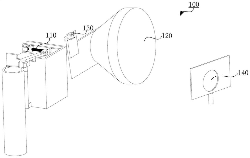
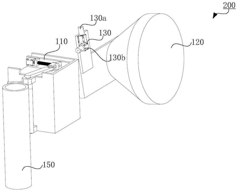
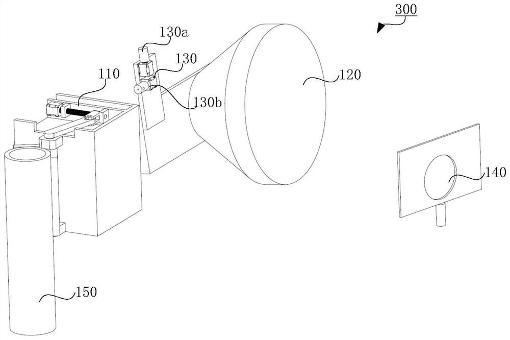
[0045] figure 1 An alignment device 100 for a microwave antenna according to a first embodiment of the present invention is shown. It can be seen from the figure that the alignment device 100 for a microwave antenna includes an adjustment mechanism 110 configured to be able to rotate the first microwave antenna ...


PUM


Abstract

The invention relates to an alignment device for a microwave antenna, a microwave antenna and an alignment method. Wherein, the alignment device for the microwave antenna includes: an adjustment mechanism configured to rotate the first microwave antenna coupled thereto to adjust the first direction and / or or an angle in the second direction; a laser emitting device configured to be mounted on the first microwave antenna and emit laser light; and a microwave antenna alignment determination device at least partially coupled to the second microwave antenna and The microwave antenna alignment determination device is configured to determine the alignment state of the first microwave antenna and the second microwave antenna according to the laser light emitted by the laser emitting device, wherein the microwave antenna alignment determination device is coupled to the second microwave antenna The direction in which the part of the laser beam is received corresponds to the direction in which the second microwave antenna receives the microwave signal from the first microwave antenna, and the first direction and the second direction are perpendicular to each other.

Description

technical field [0001] The present invention relates to a system and an alignment method for pointing equipment, in particular, to an alignment device for a microwave antenna, a microwave antenna including the alignment device, and an alignment method for a microwave antenna. Background technique [0002] In the existing antenna alignment technology, there is a method of manual positioning plus receiving level detection, and there is also an automatic alignment method of positioning plus a pan-tilt method. However, both alignment detection methods have limitations. The former uses manual methods to collect and observe the device status. At this time, the alignment is difficult, the accuracy is low, and it takes a long time; while the latter has a high degree of automation, but the mechanism is complicated, it is not easy to carry, the application scenarios are limited, and the cost is high. [0003] Specifically, the invention patent application with the patent application ...

Claims


Application Information

Patent Timeline
Patent Type & Authority Patents(China)
IPC IPC(8): H01Q1/12
CPCH01Q1/1264
Inventor 石昕邢星
Owner NORTHWEST INSTR INC
Learn More