Moving contact with small electronic tag

A technology of electronic tags and moving contacts, applied in the field of moving contacts, can solve the problems of unable to monitor the temperature of moving contacts, and achieve the effects of temperature monitoring, good metal resistance, and size reduction

Pending Publication Date: 2018-03-20
HANGZHOU ZEJI ELECTRONICS TECH CO LTD +1
View PDF5 Cites 0 Cited by
  • Summary
  • Abstract
  • Description
  • Claims
  • Application Information

AI Technical Summary

Problems solved by technology

[0004] In order to overcome the problem that the existing technology cannot monitor the temperature of the movable contact in the handcart room of the power cabinet, the present invention provides a movable contact with a miniaturized electronic label

Method used


Image

  • Moving contact with small electronic tag
  • Moving contact with small electronic tag
  • Moving contact with small electronic tag

Examples


Embodiment 1

[0034] In the handcart room of the existing power cabinet, there are two main difficulties in using the RFID tag with the temperature measurement function to monitor the temperature at the moving contact: the first is that the existing RFID tag with the temperature measurement function is relatively large. When it is connected with the moving contact body, it will interfere with the characteristics of the moving contact body; the second is that the structure of the moving contact body is special, and the RFID tag with temperature measurement function is difficult to be fixedly connected to it.

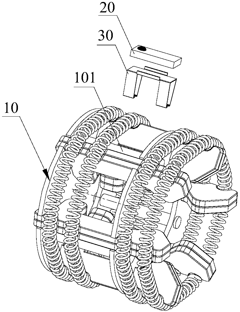
[0035] In view of this, if figure 1 and figure 2 As shown, this embodiment provides a movable contact with a miniaturized electronic label, and the movable contact with a miniaturized electronic label includes a movable contact body 10 , a miniaturized electronic label 20 and a mounting bracket 30 . The moving contact body 10 is cylindrical, and the moving contact body 10 includes a ...

Embodiment 2

[0049] Such as Figure 13 to Figure 16 As shown, this embodiment is basically the same as Embodiment 1 and its variations, except that the mounting bracket 30 further includes a supporting side plate 35 connected between the first fixing member 32 and the supporting plate 31 . When the shape or size of the miniaturized electronic tag 20 changes (such as its long side is greater than the length of the metal contact piece), in order to avoid the interference of the miniaturized electronic tag 20 on the metal contact piece, it is necessary to rotate the miniaturized electronic tag 20 at a certain angle. Install. In this embodiment, the supporting side plate 35 is arranged perpendicular to the supporting plate 31 . However, the present invention does not make any limitation thereto. In other embodiments, the angle between the supporting side plate 35 and the supporting plate 31 can be adjusted according to the size and shape of the miniaturized electronic tag 20 .

[0050] In s...


PUM


Abstract

The invention provides a moving contact with a small electronic tag. The moving contact with the small electronic tag comprises a moving contact body, the small electronic tag and a mounting bracket,wherein the moving contact body is in a cylindrical form and comprises a plurality of metal contact pieces arranged along the circumferential direction. The small electronic tag comprises a miniatureantenna and a chip connected to a feed part of the miniature antenna; the miniature antenna comprises a ceramic substrate, a radiation part, a reflection part and a connection part; the radiation partis formed on a first surface of the ceramic substrate; the reflection part is formed on a second surface of the ceramic substrate; and one end of the connection part is electrically connected with the reflection part, the other end extends to the first surface of the ceramic substrate along a side wall of the ceramic substrate and the feed part for being electrically connected with the chip is formed between the connection part and the radiation part. The mounting bracket is connected with the moving contact body and the small electronic tag, so that the small electronic tag is fixed on the metal contact pieces.

Description

technical field [0001] The invention relates to the field of radio frequency technology, and in particular to a movable contact with a miniaturized electronic label. Background technique [0002] The moving contact in the handcart room of the power cabinet is often accompanied by high-temperature heating. Long-term high-temperature heating often causes electrical accidents and causes heavy losses. Therefore, it is necessary to monitor the temperature of the moving contact to realize early warning, replace the heating element during the power maintenance process, and avoid power accidents. At present, there are several solutions for temperature monitoring of moving contacts. The first is to use a battery-powered wireless temperature monitoring device, which cannot be directly installed on the moving contact due to its large size and high cost; in addition Since the battery is used for power supply, the monitoring device needs regular maintenance due to the life of the batter...

Claims


Application Information

Patent Timeline
Patent Type & Authority Applications(China)
IPC IPC(8): H02B11/02H02B11/10H01Q1/36H01Q1/22
CPCH01Q1/2225H01Q1/36H02B11/02H02B11/10
Inventor 徐超汤兴凡薛浩王涵
Owner HANGZHOU ZEJI ELECTRONICS TECH CO LTD
Why Eureka
Try Eureka