Pneumatic clamp

A technology of pneumatic clamps and cylinders, which is applied in the field of machinery, can solve the problems of inconvenient clamping of workpieces, and achieve the effects of good clamping effect, convenient clamping of workpieces, and simple structure

Pending Publication Date: 2018-03-23
浙江青霄科技股份有限公司
View PDF1 Cites 3 Cited by
  • Summary
  • Abstract
  • Description
  • Claims
  • Application Information

AI Technical Summary

Problems solved by technology

However, when the clamping device clamps the workpiece, the workpiece must be placed between the upper and lower clamping blocks, and t

Method used


Image

  • Pneumatic clamp
  • Pneumatic clamp
  • Pneumatic clamp

Examples


Embodiment Construction

[0026] The following are specific embodiments of the present invention in conjunction with the accompanying drawings to further describe the technical solutions of the present invention, but the present invention is not limited to these embodiments.

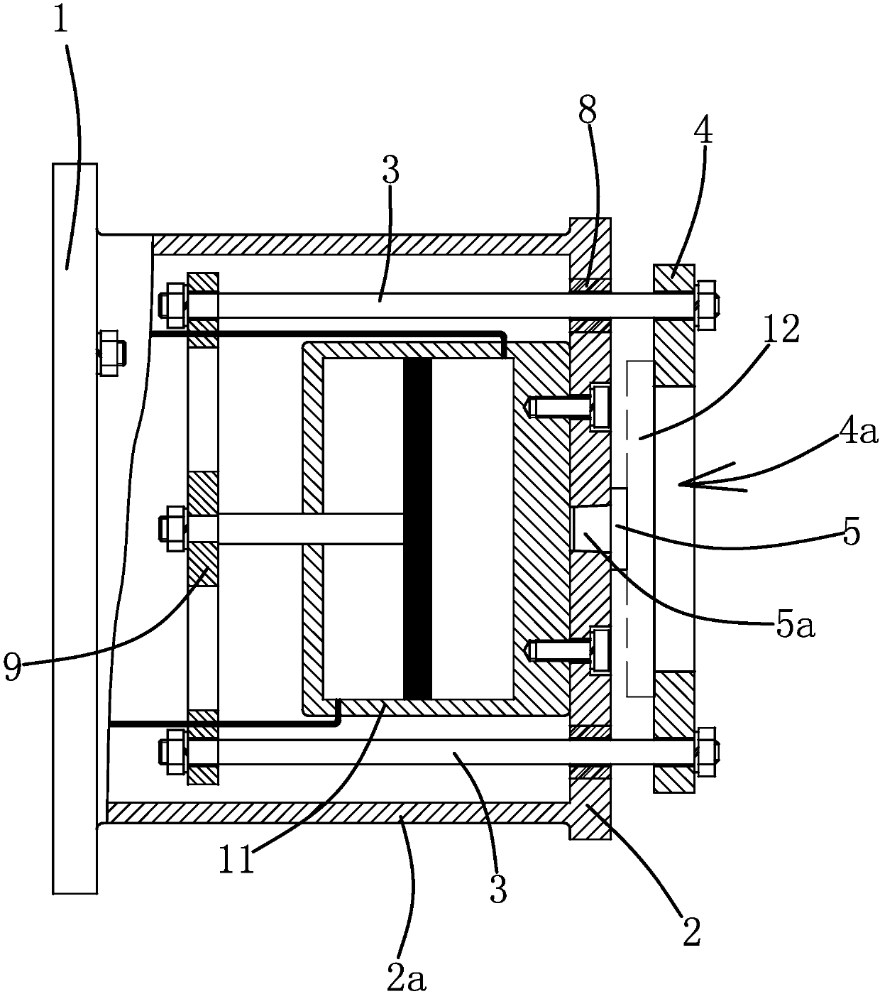
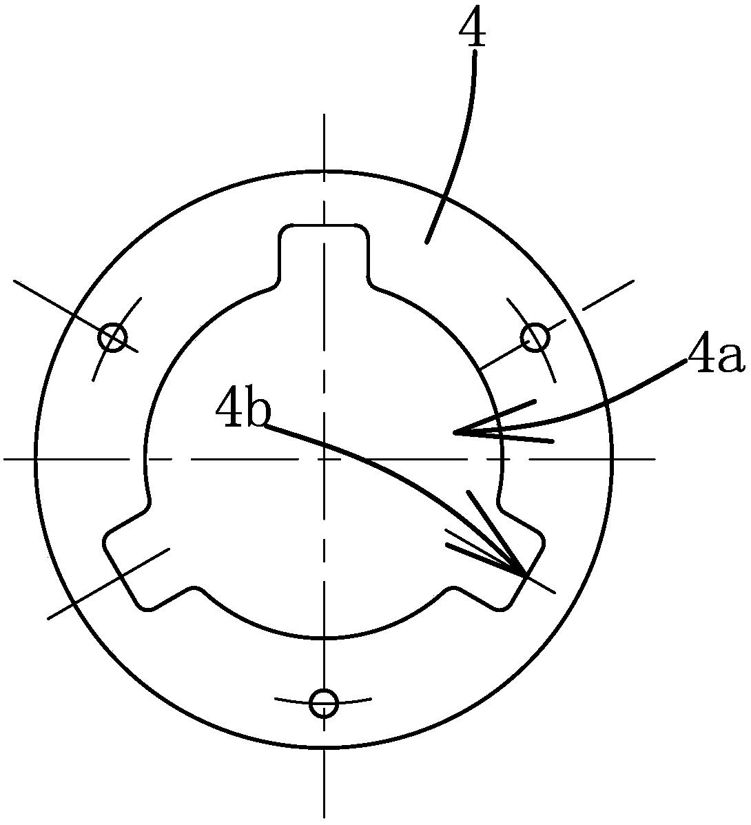
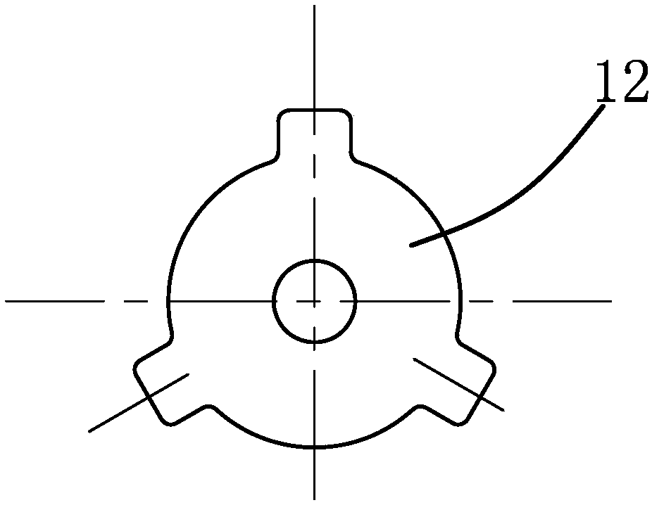
[0027] Such as Figure 1 to 3 As shown, a pneumatic clamp includes a base 1, on which a workbench 2 is provided. The outer end surface of the workbench 2 is used for a work piece 12 to rest against a positioning surface. The workbench 2 is vertically provided with three tie rods 3 and The cylinder 11 that drives the three tie rods 3 to synchronously reciprocate and translate axially. The three tie rods 3 are evenly arranged around the axis of the worktable 2. There are three sleeves 8 fixed on the worktable 2, and the tie rods 3 pass through the sleeves 8 to make the tie rods The movement of 3 has a better guiding effect, and the shaking of the lever 3 is avoided. The outer ends of the tie rods 3 are all fixedly connected with an a...


PUM


Abstract

The invention provides a pneumatic clamp, which belongs to the technical field of machinery. The utility model solves the problem that the existing pneumatic clamp is inconvenient for clamping workpieces. The pneumatic fixture comprises a base on which a workbench is arranged. The outer end surface of the workbench is used for the workpiece to lean against the positioning surface. There are several pull rods vertically arranged on the workbench and a cylinder that drives the pull rods to reciprocate and axially translate synchronously. , the outer ends of the pull rods are fixedly connected with a ring-shaped pressing block, the pressing block is arranged parallel to the outside of the workbench, and the middle part of the pressing block has an inner hole for the workpiece to pass through. The pneumatic clamp has the advantages of convenient clamping of workpieces and convenient use.

Description

Technical field [0001] The invention belongs to the technical field of machinery, and relates to a clamp, particularly a pneumatic clamp. Background technique [0002] Many industrial products need to be positioned and then processed during the production process, requiring various fixtures. For different types of products, the product's profile and positioning hole points are different, and various fixtures need to be used. The stability of the fixture itself, and the reliability of the fixture and the product workpiece, have a great impact on the final processing accuracy of the product. It has an important impact, so different product workpieces and even different clamping positions have different requirements for fixtures. [0003] For example, a valve stem chamfering pneumatic processing device (application number: 20 1 320343847.0) disclosed in the Chinese Patent Literature includes a lathe, and also includes a feeding device and a clamping device fixed on it. The clamping d...

Claims


Application Information

Patent Timeline
IPC IPC(8): B23Q3/08
CPCB23Q3/08B23Q2703/04
Inventor 王福义卢昌苗
Owner 浙江青霄科技股份有限公司
Why Eureka
Try Eureka