High-pressure charging valve body and high-pressure charging system

An inflatable system, high-pressure technology, applied in compressors, liquid displacement machines, movable measuring chambers, etc., to achieve the effect of flexible operation, long life and accurate measurement

Active Publication Date: 2018-03-23
TECHNICAL INST OF PHYSICS & CHEMISTRY - CHINESE ACAD OF SCI +1
View PDF10 Cites 0 Cited by
  • Summary
  • Abstract
  • Description
  • Claims
  • Application Information

AI Technical Summary

Problems solved by technology

[0009] Based on the above description, there is currently no

Method used


Image

  • High-pressure charging valve body and high-pressure charging system
  • High-pressure charging valve body and high-pressure charging system
  • High-pressure charging valve body and high-pressure charging system

Examples


Embodiment Construction

[0030] In order to make the purpose, technical solution and advantages of the present invention clearer, the present invention will be further described in detail below in conjunction with the accompanying drawings and embodiments. It should be understood that the specific embodiments described here are only used to explain the present invention, not to limit the present invention.

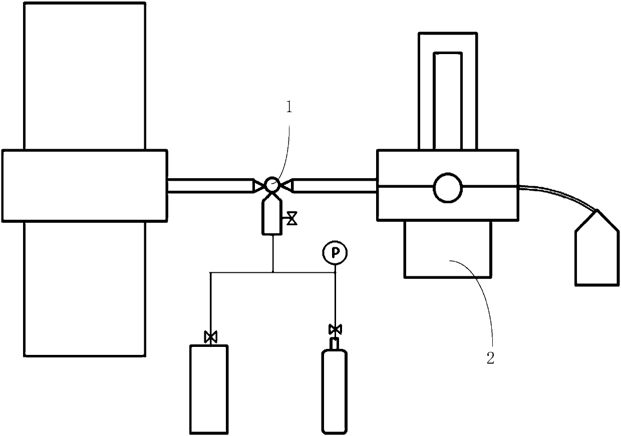
[0031] Such as figure 2 As shown, a high-pressure inflation system according to an embodiment includes a high-pressure inflation valve body 100 , a vacuum device, an air intake device and a tee pipe 200 .

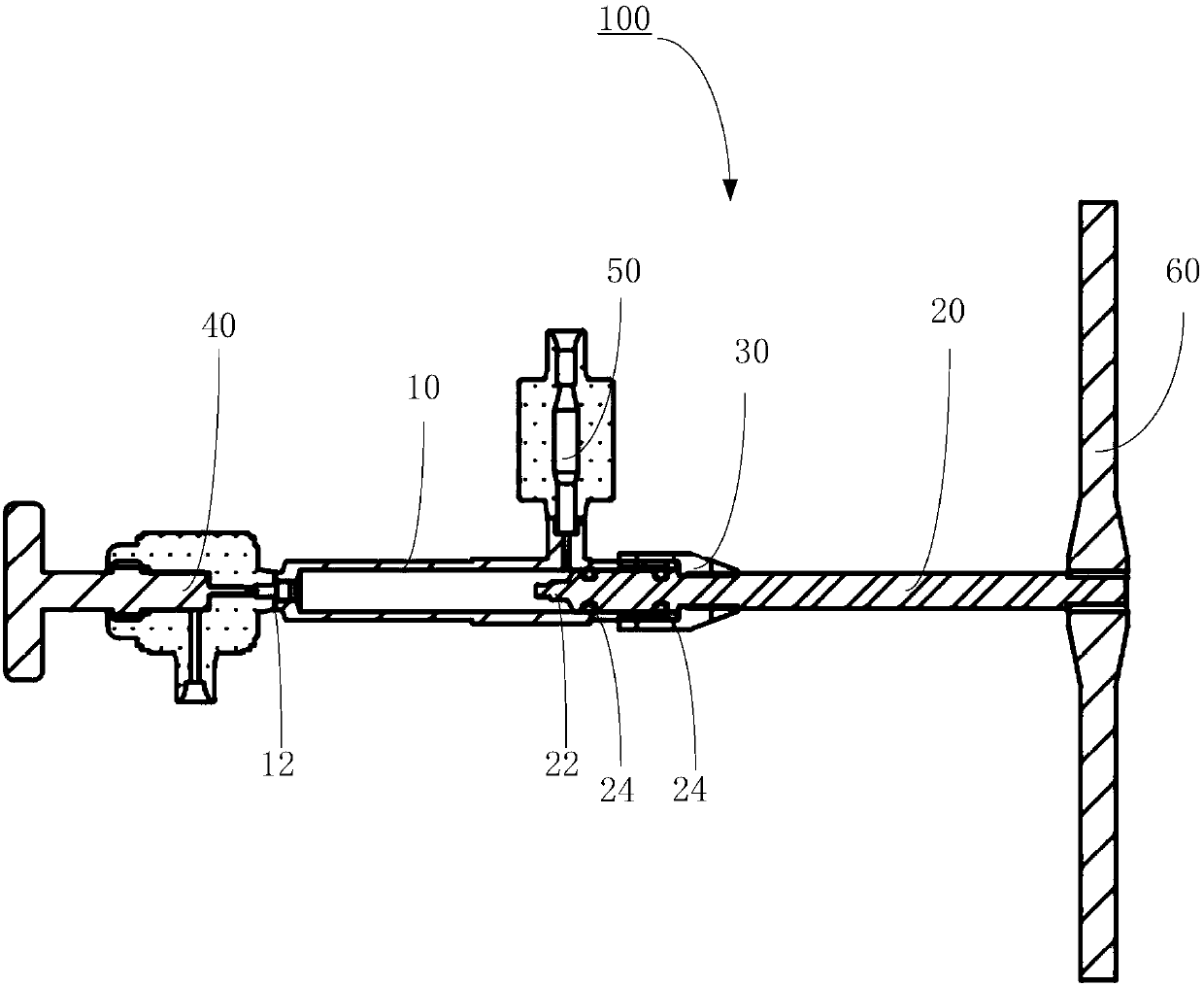
[0032] Such as image 3 and Figure 4 As shown, the high-pressure inflation valve body 100 includes a cylinder body 10 , a piston 20 , a connecting sleeve 30 , a first needle valve 40 and a second needle valve 50 .

[0033] One end of the piston 20 is arranged in the cylinder body 10, and one end of the connecting sleeve 30 is sleeved on the cylinder body 10 where the piston 20 is provided....


PUM


Abstract

The invention relates to a high-pressure charging valve body. The high-pressure charging valve body comprises a cylinder, a piston, a connecting sleeve, a first needle valve and a second needle valve,wherein one end of the piston is arranged in the cylinder, one end of the connecting sleeve sleeves one end, on which the piston is arranged, of the cylinder, the other end of the connecting sleeve is in threaded connection with the piston, the piston rotatably moves in the cylinder, the piston is in dynamic seal matching with the cylinder, the first needle valve is arranged on the end, which isfar from one end of the piston, of the cylinder, the second needle valve is arranged on the side wall of one end, which is sleeved by the connecting sleeve, of the cylinder, and the first needle valve, the cylinder and the second needle valve communicate with one another. According to the high-pressure charging valve body, the piston is in threaded fit with a connecting piece, so that the piston rotatably moves, the reaction of high-pressure air in the cylinder can be prevented, all air in the cylinder is extruded, the accurate is high, the high pressure is resistant, the operation is flexible, and milligram trace gas can be continuously added for many time by designing the appropriate size, so that accurate measurement of the gas flow is realized. In addition, the invention further provides a high-pressure charging system which adopts the high-pressure charging valve body.

Description

technical field [0001] The invention relates to the technical field of inflation devices, in particular to a high-pressure inflation valve body and a high-pressure inflation system. Background technique [0002] The solution for adding fluid in engineering is generally to fill directly after the high-pressure fluid passes through the flowmeter, and the filling amount of the fluid is generally measured by the flowmeter, and when adding gas, it is added through the gas flowmeter. At present, the gas flowmeter has the advantages of high temperature and high pressure resistance, but it cannot be filled with milligram-level gas under high temperature and high pressure conditions. In the specific engineering experiment requirements, it is necessary to add milligram-level trace gas to the high-pressure environment, so the existing flow meter cannot be used to measure the gas filling amount, and a set of mechanical valve body must be designed separately to realize the single- It ca...

Claims


Application Information

Patent Timeline
IPC IPC(8): F04B39/00F04B39/10F25B9/14G01F11/14
CPCF04B39/00F04B39/10F25B9/145G01F11/14
Inventor 陈厚磊张晓华荀玉强
Owner TECHNICAL INST OF PHYSICS & CHEMISTRY - CHINESE ACAD OF SCI
Why Eureka
Try Eureka