
Vacuum insulation plate structure

A vacuum insulation panel and vacuum technology, which is used in lighting and heating equipment, refrigeration device isolation, household appliances, etc., can solve the problems of reducing the insulation performance of insulation panels, condensation on the edges of vacuum insulation panels, etc., to improve insulation performance, easy to popularize , weaken the effect of the boundary effect

Pending Publication Date: 2018-03-23
CHANGHONG MEILING CO LTD
View PDF7 Cites 3 Cited by
  • Summary
  • Abstract
  • Description
  • Claims
  • Application Information

AI Technical Summary

Problems solved by technology

Aluminum has good heat and cold conduction properties, and can well insulate air and water to ensure the service life of the vacuum insulation panel. When the vacuum insulation panel is used, the cold energy will be transmitted along the aluminum layer, extending to half the thickness of the vacuum insulation panel and produce boundary effects, seriously reducing the thermal insulation performance of the insulation board
At the same time, the boundary effect also causes serious edge condensation problems in existing vacuum insulation panels

Method used


Image

  • Vacuum insulation plate structure
  • Vacuum insulation plate structure
  • Vacuum insulation plate structure

Examples


Embodiment Construction

[0021] In order to make the purpose, technical solutions and advantages of the embodiments of the present invention clearer, the technical solutions in the embodiments of the present invention will be clearly and completely described below in conjunction with the embodiments of the present invention. Obviously, the described embodiments are part of the present invention Examples, not all examples. Based on the embodiments of the present invention, all other embodiments obtained by persons of ordinary skill in the art without creative efforts fall within the protection scope of the present invention.

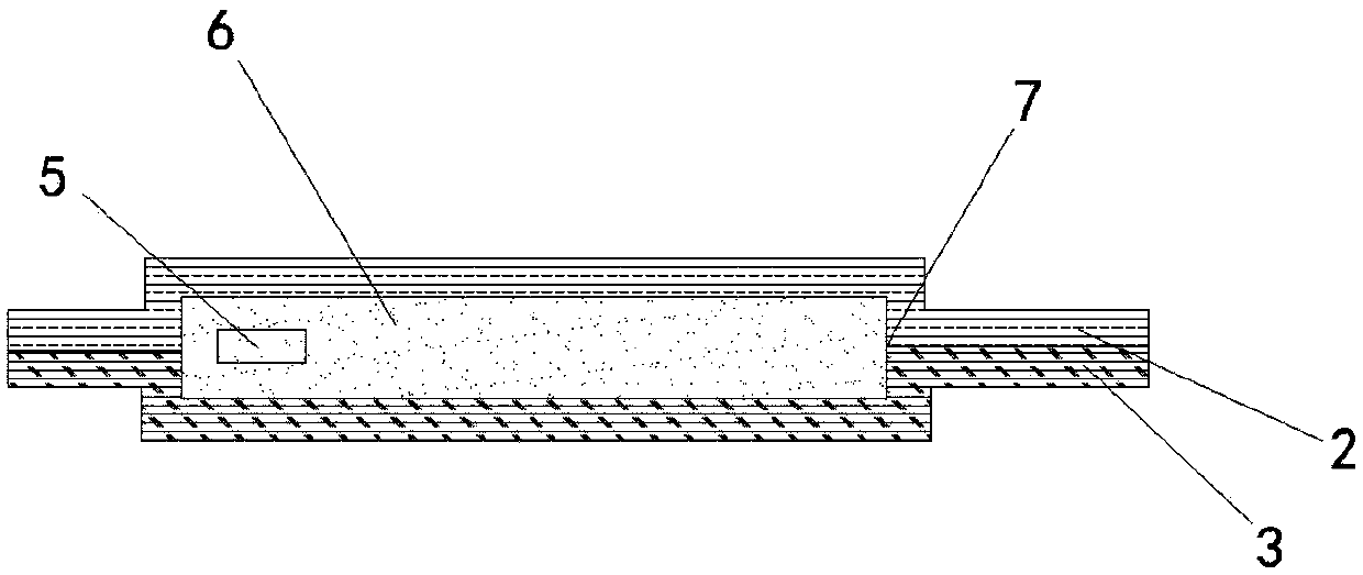
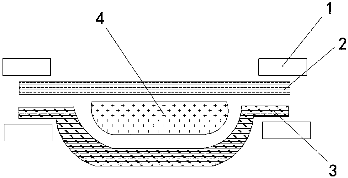
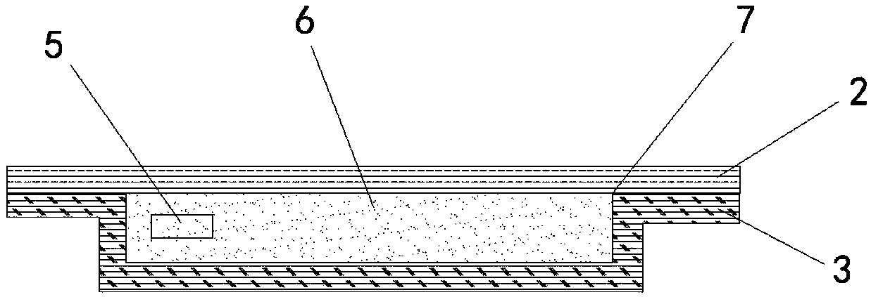
[0022] like Figure 1 to Figure 5 As shown, its structural relationship is as follows: it includes a barrier bag formed by heat-sealing the cold-surface synthetic film 2 on the cold surface and the hot-surface synthetic film 3 on the hot surface, and the joint between the cold-surface synthetic film 2 and the hot-surface synthetic film 3 is formed Heat-sealing 7; the cold surfac...


PUM


Abstract

The invention discloses a vacuum insulation plate structure and relates to the technical field of refrigeration equipment. The vacuum insulation plate structure comprises a barrier bag, wherein the barrier bag is formed a heat seal, the cold surface synthetic membrane is arranged on the cold surface, the hot surface synthetic membrane is arranged on the hot surface, the heat seal is formed at thejuncture of the cold surface synthetic membrane and the hot surface synthetic membrane. The cold surface synthetic membrane and the hot surface synthetic membrane are in an asymmetric structure, themiddle part of the hot surface synthetic membrane is bent downwards, the cross section of the hot surface synthetic membrane is in a U shape, and a vacuum containing cavity is formed in the U-shaped structure. Core materials are filled in the vacuum containing cavity, and a getter is arranged in the core materials. The hot surface synthetic membrane and the cold surface synthetic membrane are of an asymmetric structure, the heat seal is moved upwards to the surface of the synthetic membrane, the core materials and the getter are bagged, and the heat seal is disposed at the position of the surface layer of the core material port, so that the cold quantity transmission path is effectively reduced, the heat preservation performance of a heat insulation plate is improved, and meanwhile, the cold quantity transmission path is reduced, the boundary effect of the vacuum insulation plate is weakened, and the problem that the edge of the heat insulation plate is condensed due to the boundary effect is solved.

Description

technical field [0001] The invention relates to the technical field of refrigeration equipment, in particular to a vacuum insulation panel for a refrigerator. Background technique [0002] A freezer is a refrigeration device that maintains a constant low temperature. It is a common electrical appliance used for low-temperature preservation of food or other items in daily life. It is widely used in life and industry. [0003] Currently, vacuum insulation panel barrier bags for refrigerators are made of an aluminum layer and an aluminized laminated bag, enclosing the getter and core material inside. Aluminum has good heat and cold conduction properties, and can well insulate air and water to ensure the service life of the vacuum insulation panel. When the vacuum insulation panel is used, the cold energy will be transmitted along the aluminum layer, extending to half the thickness of the vacuum insulation panel and produce boundary effects, seriously reducing the thermal insul...

Claims


Application Information

Patent Timeline
Patent Type & Authority Applications(China)
IPC IPC(8): F25D23/06
CPCF25D23/065F25D2201/10
Inventor 魏邦福江峰吴园
Owner CHANGHONG MEILING CO LTD
Learn More