
Reflected wave waveform inversion method based on phase correction

A technology for phase correction and waveform inversion, applied in measurement devices, instruments, scientific instruments, etc., can solve problems such as phase inversion winding, and achieve the effects of improving linearity, high global convergence, and reducing dependence.

Active Publication Date: 2018-03-27
CHINA PETROLEUM & CHEM CORP +1
View PDF3 Cites 17 Cited by
  • Summary
  • Abstract
  • Description
  • Claims
  • Application Information

AI Technical Summary

Problems solved by technology

However, traditional phase inversion suffers from inherent winding problems

Method used


Image

  • Reflected wave waveform inversion method based on phase correction
  • Reflected wave waveform inversion method based on phase correction
  • Reflected wave waveform inversion method based on phase correction

Examples


Embodiment 1

[0055] Example 1. A method for inversion of reflected wave waveform based on corrected phase, the method comprises the following steps:

[0056] Step 1: Use the envelope information of the seismic data to correct the expression of the phase, and obtain the corrected phase information of the seismic data;

[0057] Step 2: Define the target functional expression of the reflected wave waveform inversion based on the corrected phase information, and use the adjoint state method to obtain the gradient expression of the target functional with respect to the model;

[0058] Step 3: Use the obtained gradient to update the model background field to obtain the accurate model background field of the travel time information, so as to ensure the accuracy of the travel time information;

[0059] Step 4: Finally, use the accurate model background field obtained from the travel time information to do conventional full waveform inversion to obtain high-precision velocity field modeling result...

Embodiment 2

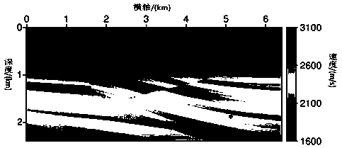
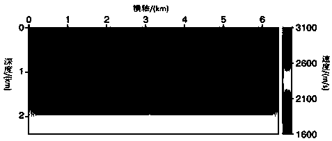
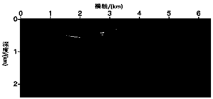
[0085] Example 2. A method of reflected wave waveform inversion based on modified phase. This method first proposes a modified phase inversion method, which uses the envelope information of seismic data to effectively avoid the winding problem of traditional phase inversion; then the modified phase The inversion method is combined with the RFWI method to define the corresponding target functional, and the adjoint equation form of the target functional is obtained by using the adjoint state method; The gradient of the target functional with respect to the model; use optimization methods, such as gradient methods, to update the background field of the model to ensure the accuracy of travel time information; finally, the obtained background velocity field is used as the input initial velocity field of traditional waveform inversion, Finely characterize the details of the model to obtain a high-precision subsurface velocity model.

[0086] Specifically include the following steps...


PUM


Abstract

The invention relates to a seismic data processing method, particularly relates to a full waveform inversion velocity field modeling method, and provides a reflected wave waveform inversion method based on a phase correction objective function. A new objective function is obtained through changing the traditional phase calculation method, and a corresponding adjoint seismic source is solved by using an adjoint state method; the objective function is optimized by an optimization method to obtain an effective background velocity field; and finally, in combination with the traditional waveform inversion, a high-precision velocity field modeling result is obtained. In view of the problem of instability of the traditional phase inversion method, the traditional phase wrapping problem is avoided, and through separation between phase and amplitude information, the corresponding objective function has higher global convergence; and middle and low wave number components in the deep layer of themodel can be effectively updated, an accurate initial model is provided for full waveform inversion, and dependence on the initial model by full waveform inversion can be effectively reduced.

Description

technical field [0001] The invention relates to a seismic data processing method, in particular to a seismic data waveform inversion velocity modeling method. Background technique [0002] Due to the large number of model parameters and the complexity of the forward modeling problem, FWI usually adopts the gradient optimization method, that is, starting from a sufficiently accurate initial model, using the adjoint state method to obtain the gradient information of the target functional in the current model and updating the model until the target Functional convergence. The target functional is usually used to measure the error between the observed data and the forward modeling data, and the selection of the target functional directly determines whether the waveform inversion problem can be successful. Tejero et al. (2015) compared several time domain full waveform inversion target functional properties in detail, and pointed out that the inversion method based on phase info...

Claims


Application Information

Patent Timeline
Patent Type & Authority Applications(China)
IPC IPC(8): G01V1/30
CPCG01V1/307G01V2210/63
Inventor 芮拥军赵翠霞王兴谋韩宏伟赵胜天赵爱国柳光华冮明川滕厚华王胜阁刘立平刘鹏翔王蓬
Owner CHINA PETROLEUM & CHEM CORP
Learn More