Rate switching method of M.2 PCIe testing fixture

A technology of rate switching and test fixtures, which is applied in faulty hardware testing methods, faulty computer hardware detection, error detection/correction, etc. It can solve the problems of unable to switch speeds, unable to test PCIeGen2 and Gen3 signals, etc., to save resources and time, easy to operate and practical, and the effect of improving work efficiency

Inactive Publication Date: 2018-03-27
ZHENGZHOU YUNHAI INFORMATION TECH CO LTD
View PDF3 Cites 5 Cited by
  • Summary
  • Abstract
  • Description
  • Claims
  • Application Information

AI Technical Summary

Problems solved by technology

But since the rate cannot be switched
[0005] Therefore, the signals of PCIe Gen2 and Gen3 cannot be t

Method used


Image

  • Rate switching method of M.2 PCIe testing fixture

Examples


Embodiment Construction

[0019] The content of the present invention is described in more detail below:

[0020] The rates for each version of the PCIe signal include:

[0021] 1. PCIe 1.0 (i.e. PCIe Gen1), the rate is 2.5Gb / s;

[0022] 2. PCIe 2.0 (that is, PCIeGen2), the rate is 5Gb / s, including Gen2 -3.5dB and -6dB two kinds of emphasis;

[0023] 3. PCIe 3.0 (that is, PCIe Gen3), the rate is 8Gb / s, including P0, P1, ..., P10.

[0024] The goal of this invention is to test PCIe Gen1, Gen2 -3.5dB and -6dB and Gen3 P7.

[0025] The implementation steps of this method are as follows:

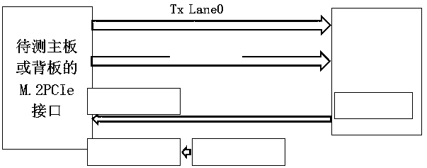
[0026] 1) M of the main board or backplane to be tested. The 2PCIe interface is connected to the test fixture. The signal lines P and N of Tx lane0 of the test fixture are respectively connected to CH3 and CH4 of the oscilloscope through the SMA-SMA cable, and the P and N of the clock signal are respectively connected to CH1 and CH2 of the oscilloscope. The two groups are the signals to be tested. like figure 1 sh...


PUM


Abstract

The invention provides a rate switching method of an M.2 PCIe testing fixture, and relates to the technical field of M.2 PCIe interface testing. According to the method, 100MHz 1ms pulses are input tolane0 of an M.2 PCIe port of a mainboard or a to-be-tested backboard, rate switching is triggered, every pulsing triggers switching of the rate once, and the switching sequence is PCIe Gen1->Gen2 -3.5dB->Gen2 -6dB->Gen3 P0->Gen3 P1->...->Gen3 P10->Gen1, and then a loop is formed. Great convenience is brought to testing of an M.2 PCIe interface, the resource and time are saved, and the work efficiency is improved.

Description

technical field [0001] The present invention relates to M. 2PCIe interface testing technology, especially related to a kind of M. 2 Rate switching method of PCIe test fixture. Background technique [0002] M. 2 interface, which is a new interface specification introduced by Intel to replace MSATA. M. 2 is a new generation of interface standards developed by Intel, which has the characteristics of smaller size and faster interface. And M. 2 Interface SSD is divided into SATA and PCI-E, the theoretical bandwidth of SATA3.0 channel is 6Gb / s, the motherboard M. The bandwidth of the 2 interface through the PCI-E channel transmission channel is 10Gb / s. [0003] Currently the main board of the server or M. 2PCIe backplane is testing PCIe M. 2 interface signal, to use a special test fixture PCI Expresss M. 2 Host Test Adapter. M. 2 interfaces. M. The 2PCIe interface test fixture has 4 pairs of Lanes plus a pair of differential clock signals, and each pair of lanes in...

Claims


Application Information

Patent Timeline
IPC IPC(8): G06F11/22G06F13/40G06F13/42
CPCG06F11/221G06F11/2273G06F13/4022G06F13/4221G06F2213/0026
Inventor 吴忠良
Owner ZHENGZHOU YUNHAI INFORMATION TECH CO LTD
Why Eureka
Try Eureka