Water level power variable resistance device

A resistive device, variable technology, applied in the field of physical electricity

Inactive Publication Date: 2018-03-27
防城港市奥氏蓝科技有限公司
View PDF3 Cites 5 Cited by
  • Summary
  • Abstract
  • Description
  • Claims
  • Application Information

AI Technical Summary

Benefits of technology

This patented technology allows for monitoring the movement or positioning of objects along rails during operation at different levels within specific areas such as buildings or industrial facilities. It uses a special type of material called resistive rods attached inside sliding tubes made from plastic materials like polyethylene (PE) which helps it work better when there are no more than two floors above them. Whenever one floor needs maintenance or other things happening over time, they cause problems because their movements may be affected negatively affecting safety measures designed around these structures. By measuring how well each part has been moved between certain points throughout its entire lifecycle, researchers could help identify issues earlier before any damage occurs due to environmental factors or equipment malfunctions.

Problems solved by technology

Technological Problem addressed in this patents relates to how to calculate or estimate the amount of resistance needed for use in industrial applications like welded connections. However, existing methods often result in errors due to variations in environmental conditions during manufacturing processes. These include variables including ambient air humidity, indoor light levels, time duration from production start up until end of life, distance traveled over long distances before reaching maximum performance level. Additionally, conventional techniques require multiple measurements, making them difficult to implement within small devices.

Method used


Image

  • Water level power variable resistance device

Examples


Embodiment Construction

[0019] A water level dynamic variable resistance device will be further described below in conjunction with the accompanying drawings.

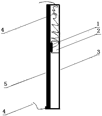
[0020] figure 1 It is a side middle cross-sectional view of a water level dynamic variable resistance device. The water level dynamic variable resistance device in the figure is placed on a vertical horizontal plane. A vertical slide rail cylinder 3 is the main component, and the inner side of the slide rail cylinder 3 is fixed and installed A resistance rod 5, the lower part of the resistance rod 5 is connected with a conductive wire 4, and the resistance rod 5 is covered with the left side wall of the whole slide rail cylinder 3. There is also a float 2 in the middle of the inside of the slide rail tube 3 that can move up and down, and this movement is driven by the change of the water level immersed. An electric contact 1 is attached to the left side of the float 2, and the electric contact 1 is connected with a conductive wire 4. The ele...


PUM


Abstract

The invention discloses a water level power variable resistance device, mainly comprising a resistor rod, a sliding rail cylinder, a floater, an electric contact and conductive wires; the device is characterized in that resistor rod is installed on the inner side face of a sliding rail cylinder; the floater can slide up and down in the sliding rail cylinder; the electric contact is fixedly installed on the floater and is in contact with the resistor rod in a sliding way; one conductive wire is connected with the lower part of the resistor rod, and the other conductive wire is connected with the electric contact; the two conductive wires can be respectively used as an input conductive wire and an output conductive wire of a variable resistor. According to the water level power variable resistance device, the electric contact is enabled to slide on the resistor rod by means of the variable power of the water level, so that the effective length of the resistor rod is changed, the resistance value is changed, and the passing current is changed; the changes are expressed through the relevant instruments, so that people can correctly monitor the changes in the water level.

Description


Claims


Application Information

Patent Timeline
Owner 防城港市奥氏蓝科技有限公司
Why Eureka
Try Eureka