Quick assembling device for permanent magnet rotating machine

A technology for assembling devices and rotating machines, which is applied in the direction of electromechanical devices, manufacturing motor generators, electric components, etc., can solve problems such as difficult to separate, cannot be applied to permanent magnet rotating machines, stator and rotor collisions, and achieve the effect of preventing deviations

Active Publication Date: 2018-03-27
江苏祝尔慷电机节能技术有限公司
View PDF4 Cites 5 Cited by
  • Summary
  • Abstract
  • Description
  • Claims
  • Application Information

AI Technical Summary

Problems solved by technology

[0002] The permanent magnet motor has main structural parts such as front and rear end covers, stator and rotor. Since the rotor is equipped with magnetic steel, the rotor has a strong adsorption force as a whole, and it is easy to cause collisions between the stator and rotor due to gravity during assembly. If only There is an electromagnetic release device that can realize the rapid release of the rotor, but there is still a chance that the stator and rotor will be adsorbed together and difficult to separate, and cannot be assembled in place, or even scrapped, and it is easy to cause personal injury. The traditional vertical or horizontal installation process has been proved Unable to meet mass production requirements
For this reason, those skilled in the art have proposed a permanent magnet motor rapid assembly device that is easy to use and control, can realize rapid guide installation of the rotor, significantly improves work efficiency, has high reliability, and has a long service life, so as to solve the problems in the above-mentioned background technology. The proposed problem, such as the patent No. CN 205753879U, includes a rotor, a stator, a front end cover, a rear end cover, a mould, a base, a bracket and a hydraulic cylinder, the inside of the stator is provided with a rotor, and the upper part of the stator is provided with a The front end cover, the lower part of the stator is provided with a rear end cover, the bottom of the rear end cover is provided with a mold, and the bottom of the mold is provided with a base. Although the problem of inconvenient control is solved, there are still permanent magnets that cannot be applied to different models. Turning machine

Method used


Image

  • Quick assembling device for permanent magnet rotating machine
  • Quick assembling device for permanent magnet rotating machine
  • Quick assembling device for permanent magnet rotating machine

Examples


Embodiment Construction

[0021] The following will clearly and completely describe the technical solutions in the embodiments of the present invention with reference to the accompanying drawings in the embodiments of the present invention. Obviously, the described embodiments are only some, not all, embodiments of the present invention. Based on the embodiments of the present invention, all other embodiments obtained by persons of ordinary skill in the art without making creative efforts belong to the protection scope of the present invention.

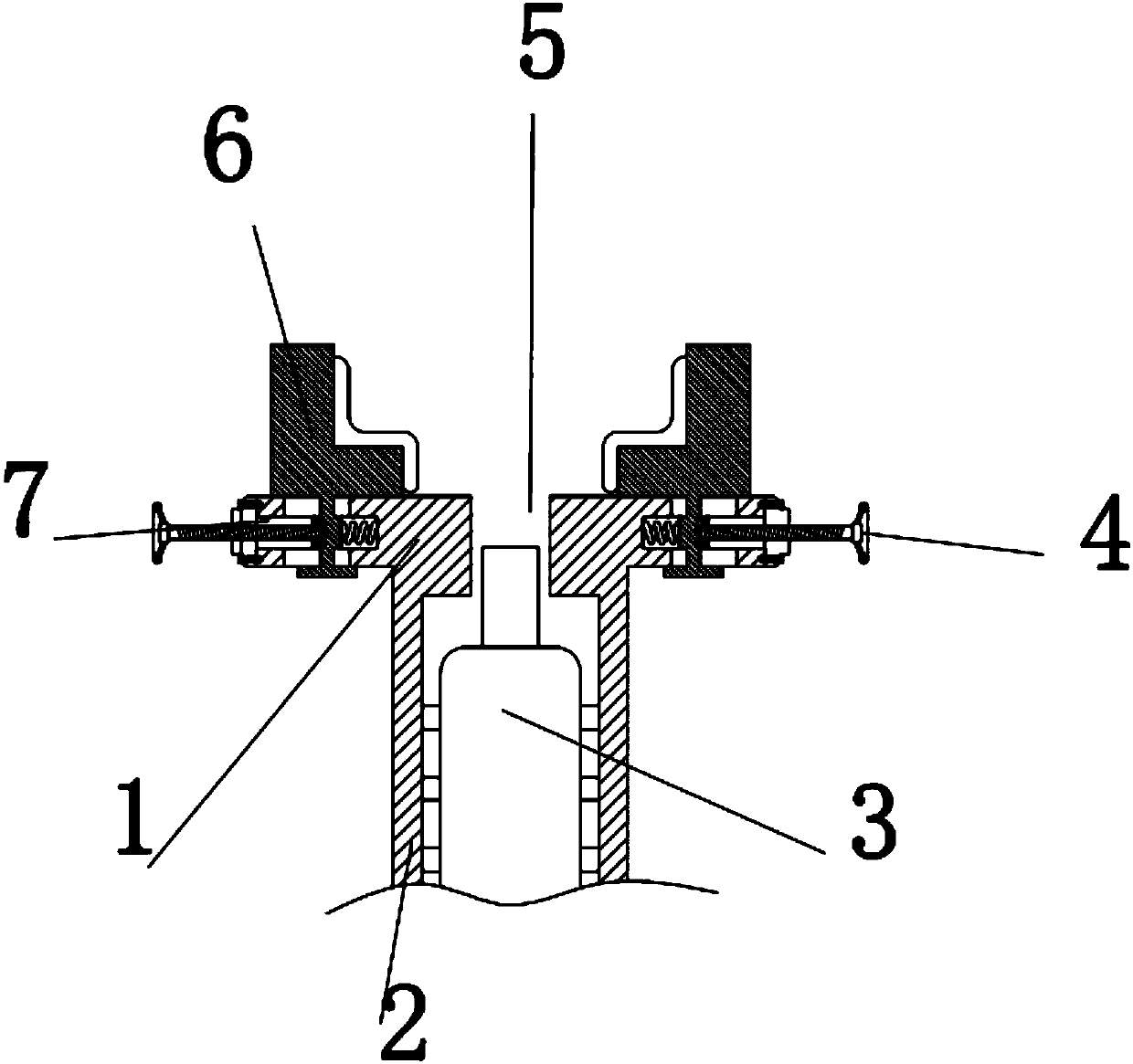
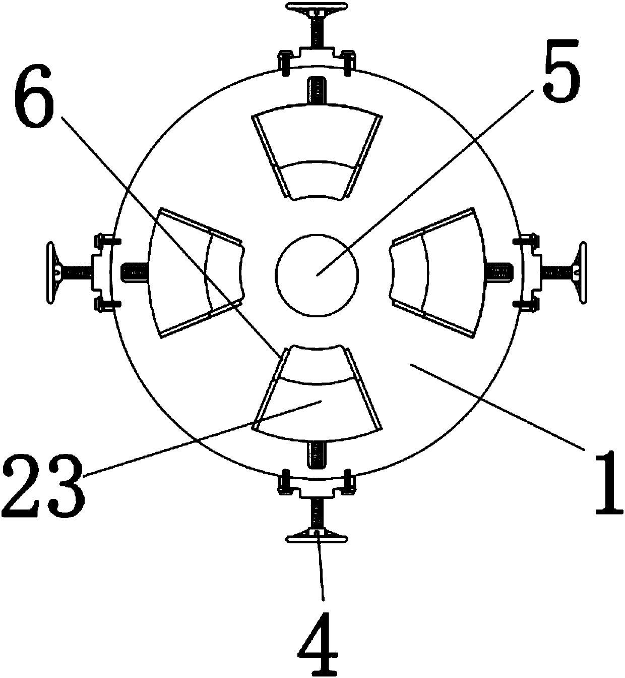
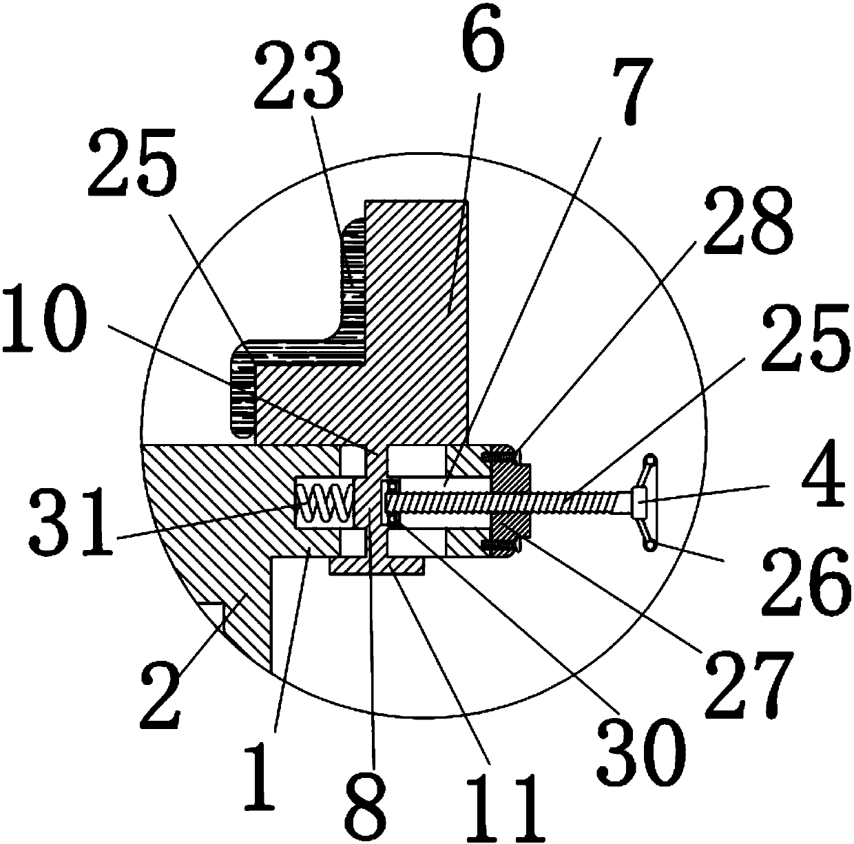
[0022] see Figure 1-5 , the present invention provides a technical solution: a quick assembly device for a permanent magnet rotating machine, including a bracket 2 and a hydraulic machine 3, the inside of the bracket 2 is provided with a hydraulic machine 3, the bracket 2 is used to fix the hydraulic machine 3, and the upper end of the bracket 2 is provided with a circle Disk 1, the center of the disk 1 is provided with a circular hole 5, the outer circumfere...


PUM


Abstract

The invention discloses a quick assembling device for a permanent magnet rotating machine, which comprises a support and a hydraulic press, wherein the support is internally provided with the hydraulic press; a bolt rod is connected with a sliding block through a bearing; the right-side surface of the bolt rod is provided with a fastener; the left end of the fastener is connected with a disc; andthe fastener is in matched connection with the bolt rod. Through rotating the bolt rod, matched connection between the bolt rod and the fastener enables the bolt rod to push the sliding block to move,the sliding block moves to drive a clamping block to move, the size of the shell of the permanent magnet rotating machine which can be fixed by the clamping blocks can be adjusted through adjusting the distance between the clamping blocks, the support can support the disc, a convex block is arranged on the upper surface of a gasket, the trajectory of the gasket can be limited through the matchedconnection between the convex block and a first groove, the sliding block can be further limited through limiting the gasket, and deviation of the movement of the sliding block can be prevented.

Description

technical field [0001] The invention relates to the technical field of permanent magnet rotating machines, in particular to a quick assembly device for permanent magnet rotating machines. Background technique [0002] The permanent magnet motor has main structural parts such as front and rear end covers, stator and rotor. Since the rotor is equipped with magnetic steel, the rotor has a strong adsorption force as a whole, and it is easy to cause collisions between the stator and rotor due to gravity during assembly. If only There is an electromagnetic release device that can realize the rapid release of the rotor, but there is still a chance that the stator and rotor will be adsorbed together and difficult to separate, and cannot be assembled in place, or even scrapped, and it is easy to cause personal injury. The traditional vertical or horizontal installation process has been proved Unable to meet mass production requirements. For this reason, those skilled in the art have...

Claims


Application Information

Patent Timeline
Patent Type & Authority Applications(China)
IPC IPC(8): H02K15/03H02K15/16
CPCH02K15/03H02K15/16
Inventor 刘和来
Owner 江苏祝尔慷电机节能技术有限公司
Why Eureka
Try Eureka