Adjustable transmitter power amplification mechanism for UHF frequency band

A transmitter and power amplifier technology, applied in the field of transmitters, can solve the problem that the power amplifier cannot adapt to different frequency bands, and achieve the best power output effect

Pending Publication Date: 2018-03-27
江苏德是和通信科技有限公司
View PDF0 Cites 0 Cited by
  • Summary
  • Abstract
  • Description
  • Claims
  • Application Information

AI Technical Summary

Problems solved by technology

[0003] Purpose of the invention: In view of the above technical problems, the present invention provides an adjustable transmitter power amplifier mechanism for the UHF frequency band, which is used to solve the problem that a power amplifier cannot adapt to different frequency bands

Method used


Image

  • Adjustable transmitter power amplification mechanism for UHF frequency band
  • Adjustable transmitter power amplification mechanism for UHF frequency band
  • Adjustable transmitter power amplification mechanism for UHF frequency band

Examples


Embodiment 1

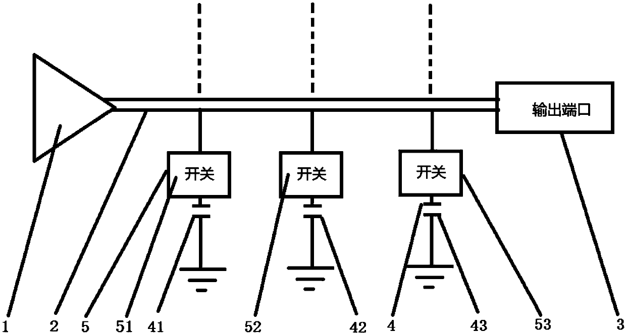
[0023] See figure 1 , An adjustable transmitter power amplifier mechanism for UHF frequency band, including power amplifier 1, microstrip transmission line 2, output port 3. One end of the microstrip transmission line 2 is connected to the output end of power amplifier 1, and the other end is connected to the input end of output port 3. ; The microstrip transmission line 2 is connected with a regulating capacitor component 4, and a radio frequency switch 5 is arranged between the regulating capacitor component 4 and the microstrip transmission line 2. One end of the regulating capacitor component 4 is connected to one end of the radio frequency switch 5, and the other end is grounded, and the regulating capacitor The component 4 adjusts the capacitance to a predetermined capacitance value as required. Among them, the number of the radio frequency switch 5 and the adjusting capacitor component 4 can be set as required.

[0024] In this embodiment, the number of radio frequency swi...

Embodiment 2

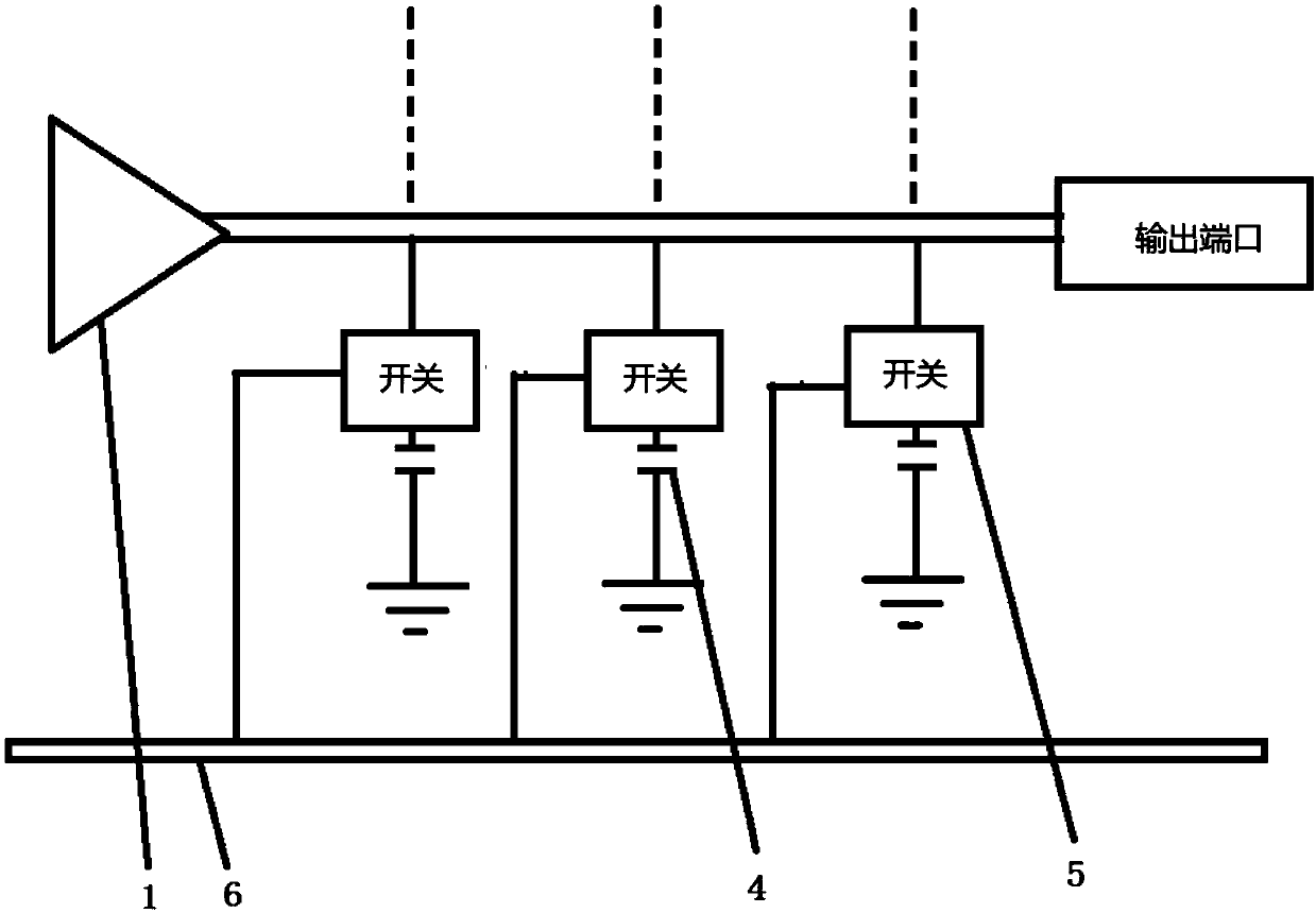
[0028] See figure 2 The difference between this embodiment and the first embodiment is that it also includes a switch bus 6, which is connected to a radio frequency switch 51, a radio frequency switch 52, and a radio frequency switch 53 respectively. The working state of the radio frequency switch 51, the radio frequency switch 52, and the radio frequency switch 53 are controlled through the switch bus 6.

Embodiment 3

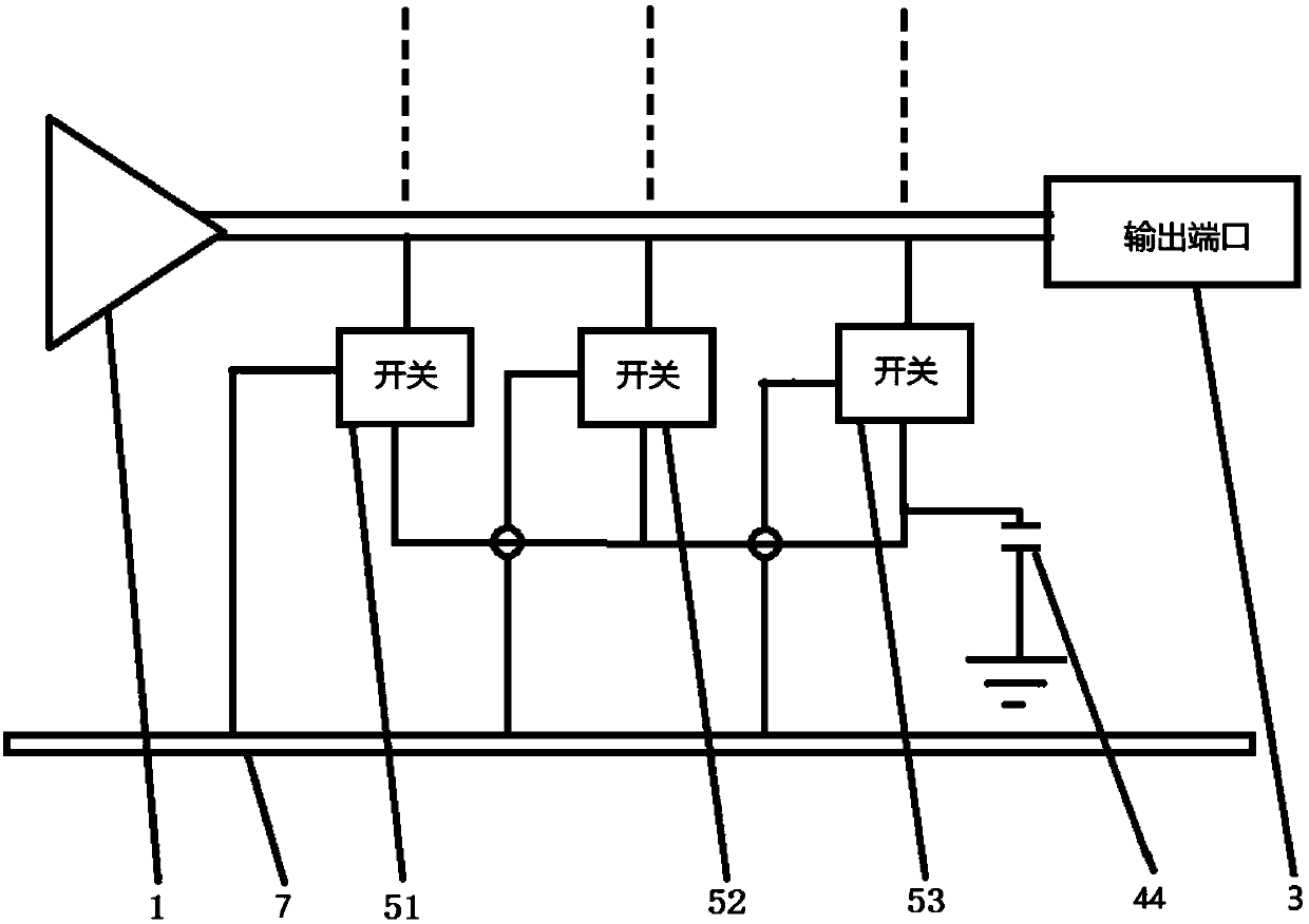
[0030] See image 3 The difference between this embodiment and Embodiment 1 is that: in this embodiment, a switch bus 2 7 is also included. Among them, the adjusting capacitor component 4 is an adjustable capacitor 44. Radio frequency switch one 51, radio frequency switch two 52, and radio frequency switch three 53 are arranged in parallel, and switch bus two 7 are respectively connected to radio frequency switch one 51, radio frequency switch two 52 and radio frequency switch three 53;

[0031] Among them, the radio frequency switch 51, the radio frequency switch 52, and the radio frequency switch 53 are connected in parallel with the adjustable capacitor 44 in series, and the output ends of the radio frequency switch 51, the radio frequency switch 52, and the radio frequency switch 53 are respectively connected to the microstrip transmission line 2.

[0032] In this embodiment, the capacitance value of the adjustable capacitor 44 is adjusted, and at the same time one of the radi...


PUM


Abstract

The invention provides an adjustable transmitter power amplifier mechanism for UHF frequency band, including a power amplifier, a microstrip transmission line and an output port, one end of the microstrip transmission line is connected to the output end of the power amplifier, and the other end is connected to the input end of the output port; The transmission line is connected with an adjusting capacitor component, and a radio frequency switch is arranged between the adjusting capacitor component and the microstrip transmission line. One end of the adjusting capacitor component is connected to one end of the radio frequency switch, and the other end is grounded. The adjusting capacitor component adjusts the capacitance to a predetermined capacitance value as required. The adjustable transmitter power amplifier mechanism for the above-mentioned UHF frequency band is equipped with an adjustable capacitor component and a radio frequency switch, and the capacitor can be adjusted to a predetermined capacitance value as required. Since the impedance and frequency have a matching relationship, the impedance of different frequencies can be in the best working state of the power amplifier. requirements, to meet the adjustable function of the power amplifier mechanism of the adjustable transmitter in the UHF frequency band, without sacrificing the performance of some power amplifiers, and to achieve the best power output of the power amplifier mechanism at different frequencies.

Description

Technical field [0001] The invention relates to the field of transmitters, in particular to an adjustable transmitter power amplifier mechanism for UHF frequency band. Background technique [0002] With the development of the times, analog TV at home and abroad is gradually shutting down, and digital TV has been rolled out on a large scale. Common digital TV modes are DTMB, DVB-T and ASDB-T. Deploy digital TV based on DTMB in the country. Digital TV can work in VHF (very high frequency) frequency band and UHF (very high frequency) frequency band. VHF frequency band is 167~223MHz, UHF frequency band is 470~860MHz. The VHF frequency band is relatively narrow, and the key component of the digital TV transmitter is the RF power amplifier. Generally, the bandwidth of the VHF frequency band is relatively narrow, and it is easy to cover the whole frequency band with one power amplifier. UHF frequency band spans 390MHz, usually divided into multiple frequency bands to design power a...

Claims


Application Information

Patent Timeline
Patent Type & Authority Applications(China)
IPC IPC(8): H04N5/38
CPCH04N5/38
Inventor 隋强王轶冬王典进徐芳赵永晓王彤光姜长伟刘进华
Owner 江苏德是和通信科技有限公司
Why Eureka
Try Eureka