An electric drive well cementing cement truck

A cementing and electric drive technology, applied in wellbore/well components, sealing/packaging, earth-moving drilling, etc. The effect of high power density

Active Publication Date: 2022-05-13
BAOJI PETROLEUM MASCH CO LTD +2
View PDF15 Cites 0 Cited by
  • Summary
  • Abstract
  • Description
  • Claims
  • Application Information

AI Technical Summary

Problems solved by technology

[0004] The purpose of the present invention is to provide an electric drive cement truck, which solves the problem of low power of the cement truck in the prior art

Method used


Image

  • An electric drive well cementing cement truck
  • An electric drive well cementing cement truck
  • An electric drive well cementing cement truck

Examples


Embodiment Construction

[0021] The present invention will be described in detail below in conjunction with the accompanying drawings and specific embodiments.

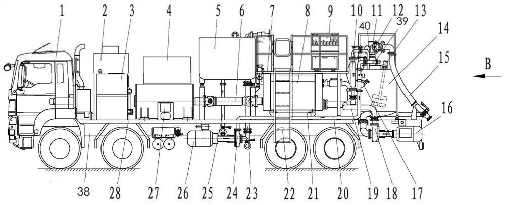
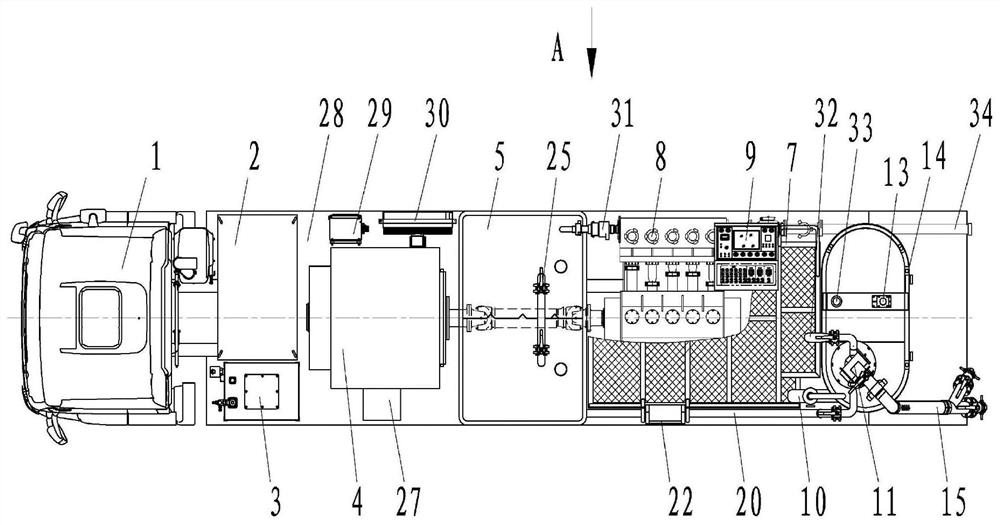
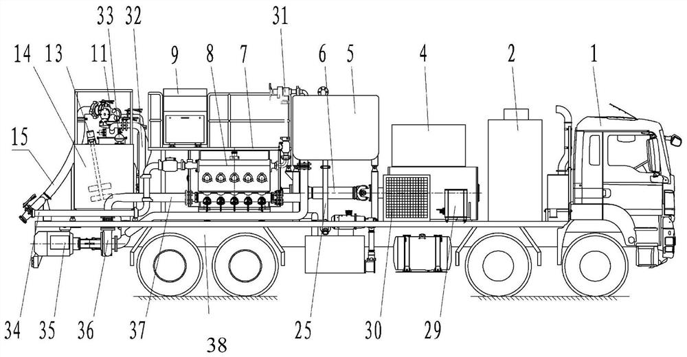
[0022] An electric drive well cementing cement truck of the present invention, such as figure 1 Shown, comprise automobile chassis 1, on the crossbeam 38 of automobile chassis 1, be fixedly connected with overhaul platform 28, be fixedly connected with mud mixing tank 14 on the overhaul platform 28, be provided with mixer 11, agitator 13 and liquid mixer 14 tops. One end of the water valve 39 and one end of the ash valve 40 are welded on the mixer 11 respectively. The other end of the water valve 39 is connected to the discharge port of the clean water pump 24 through the clean water manifold 20, and the suction port of the clean water pump 24 passes through The water suction manifold 23 is connected to the bottom of the metering tank 5, and the bottom of the metering tank 5 is fixed on the maintenance platform 28 by four legs. The bottom of ...


PUM


Abstract

The invention discloses an electric drive well cementing cement truck, which comprises a car chassis, an inspection platform is fixedly connected to the girder of the car chassis, a mud mixing tank is fixedly connected to the repair platform, and a mixer and agitator are arranged on the upper part of the mud mixing tank. The mixer is connected to the water channel and the ash channel through pipelines; there are two outlets at the bottom of the mixing tank, one outlet is connected to the first sand pump and the circulating mud manifold in turn, and the outlet of the circulating mud manifold is respectively connected to the density meter and the second One end of the secondary mixing manifold, the other end of the secondary mixing manifold is connected to the slurry inlet of the mixer; the other outlet of the mixing tank is connected to the second sand pump, booster manifold, and plunger pump in sequence , Discharge manifold, and the discharge manifold is also connected with a pressure relief manifold. The beneficial effects of the present invention are: convenient installation and connection of equipment; high power density; high working efficiency of the whole vehicle; clean energy and zero discharge.

Description

technical field [0001] The invention belongs to the technical field of cement trucks for well cementing, and in particular relates to an electrically driven cement truck for well cementing. Background technique [0002] With the continuous development of shale gas resources in my country, the frequency of cementing operations in ultra-deep wells and complex formations is increasing. High pressure, large displacement, and long-term uninterrupted cementing operations have gradually become the norm. Conventional single-machine single-pump, double-machine double-pump and even thousand-type pump cementing trucks cannot fully meet the construction requirements due to power limitations. [0003] When a conventional cement truck is in operation, the diesel engine drives the cementing plunger pump through the gearbox through the transmission shaft, and the hydraulic system of the vehicle is driven by the chassis engine. The diesel engines and gearboxes commonly used in the market are...

Claims


Application Information

Patent Timeline
Patent Type & Authority Patents(China)
IPC IPC(8): E21B33/13
CPCE21B33/13
Inventor 李小兵李鹏白兰昌马太清刘娇利李欢范松
Owner BAOJI PETROLEUM MASCH CO LTD
Why Eureka
Try Eureka