
High-cooling performance power cabinet

A high heat dissipation, power cabinet technology, applied in the direction of electrical components, electrical equipment structural parts, cooling/ventilation/heating transformation, etc., can solve the problems of poor heat dissipation of power cabinets, improve heat dissipation, make up for defects in use, Avoid the burnout effect

Inactive Publication Date: 2018-03-27
ANHUI TIGER ELECTRICAL TECH
View PDF0 Cites 17 Cited by
  • Summary
  • Abstract
  • Description
  • Claims
  • Application Information

AI Technical Summary

Problems solved by technology

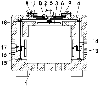
[0003] The purpose of the present invention is to solve the problem that the structure of the power cabinet in the prior art is generally relatively simple, and the heat dissipation of the power cabinet is poor, and a high heat dissipation power cabinet is proposed.

Method used


Image

  • High-cooling performance power cabinet
  • High-cooling performance power cabinet
  • High-cooling performance power cabinet

Examples


Embodiment Construction

[0016] The following will clearly and completely describe the technical solutions in the embodiments of the present invention with reference to the accompanying drawings in the embodiments of the present invention. Obviously, the described embodiments are only some, not all, embodiments of the present invention.

[0017] In describing the present invention, it should be understood that the terms "upper", "lower", "front", "rear", "left", "right", "top", "bottom", "inner", " The orientation or positional relationship indicated by "outside", etc. is based on the orientation or positional relationship shown in the drawings, and is only for the convenience of describing the present invention and simplifying the description, rather than indicating or implying that the referred device or element must have a specific orientation, so as to Specific orientation configurations and operations, therefore, are not to be construed as limitations on the invention.

[0018] refer to Figure ...


PUM


Abstract

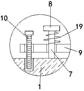
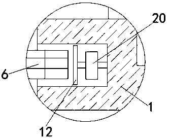
The invention discloses a high heat dissipation power cabinet, comprising a main cabinet body and a drive motor, the drive motor is fixedly connected to the top of the main cabinet body, the top of the main cabinet body is provided with a mounting groove, and the drive motor The output shaft runs through the top of the main cabinet and extends into the installation groove. One end of the output shaft extension of the driving motor is fixedly connected with a plurality of first fan blades, and a worm is connected in rotation in the installation groove. The output of the driving motor The first gear meshed with the worm is fixedly sleeved on the shaft, and the inner wall of the main cabinet body is provided with two symmetrically arranged cavities, and the two ends of the worm respectively pass through the inner walls of both sides of the installation groove and extend to the hollow. The inner top of the installation groove is provided with two symmetrically arranged ventilation openings. The invention improves the heat dissipation in the power cabinet through the arrangement of multiple transmission mechanisms, avoids burning out of electric equipment in the power cabinet due to excessive temperature, and makes up for the use defects of the existing power cabinet.

Description

technical field [0001] The invention relates to the technical field of power equipment, in particular to a high heat dissipation power cabinet. Background technique [0002] Power equipment mainly includes two categories: power generation equipment and power supply equipment. Among them, the power cabinet is a storage device for storing voltmeters, ammeters or other electrical equipment, and is used to protect these equipment from open circuits, bumps and other accidents. However, the structure of the existing power cabinets is generally relatively simple, and the heat dissipation of the power cabinets is relatively poor, which easily causes the electric equipment inside the power cabinets to burn out due to excessive temperature, and has certain defects in use. Contents of the invention [0003] The purpose of the present invention is to solve the problems of the prior art that the structure of the power cabinet is generally relatively simple and the heat dissipation of ...

Claims


Application Information

Patent Timeline
Patent Type & Authority Applications(China)
IPC IPC(8): H05K7/20
CPCH05K7/20172H05K7/20181
Inventor 王磊陈学毅王超
Owner ANHUI TIGER ELECTRICAL TECH
Learn More