Suction disc device and element transfer method

A suction cup and component technology, applied in the field of suction cup devices with patterned conductive layers, can solve the problems of high cost, increased cost, unfavorable use of mechanical picking methods, etc., and achieves the effect of avoiding static electricity

Active Publication Date: 2018-03-30
UNIMICRON TECH CORP
View PDF6 Cites 1 Cited by
  • Summary
  • Abstract
  • Description
  • Claims
  • Application Information

AI Technical Summary

Problems solved by technology

However, as the size of components becomes smaller and smaller, the traditional method of handling will lead to a significant increase in cost
In addition, when electronic parts enter micro- or nano-scale dimensions, mechanical handling methods are not conducive to use
Although some people propose to use novel methods such as suction nozzles to replace the mechanical picking method, but it has the disadvantages of high cost and difficult manufacturing of jigs
Therefore, the assembly of tiny components is a bottleneck

Method used


Image

  • Suction disc device and element transfer method
  • Suction disc device and element transfer method
  • Suction disc device and element transfer method

Examples


Embodiment Construction

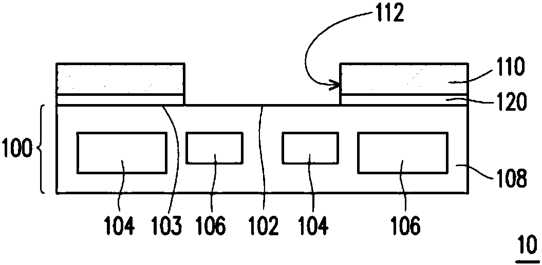
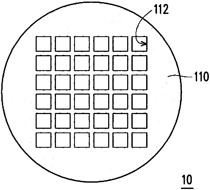
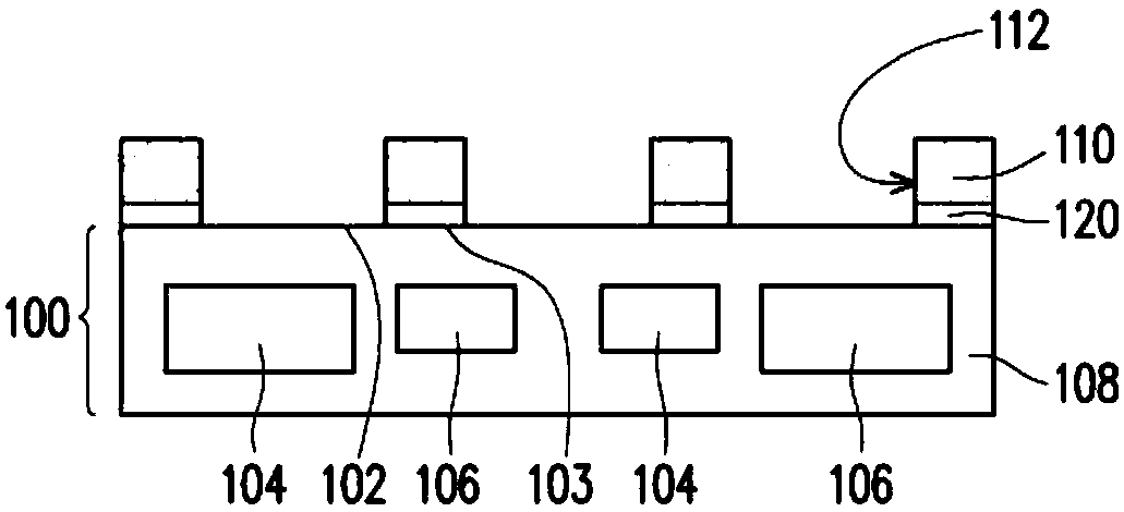
[0021] Figure 1A is a schematic cross-sectional view of a suction cup device according to an embodiment of the present invention, and Figure 1B It is a schematic top view of a suction cup device according to an embodiment of the present invention. Please also refer to Figure 1A and Figure 1B , in this embodiment, the chuck device 10 includes an electrostatic chuck 100 and a patterned conductive layer 110 . The electrostatic chuck 100 , for example, includes at least one positive electrode 104 , at least one negative electrode 106 , and an insulating layer 108 surrounding the positive electrode 104 and the negative electrode 106 , wherein charges are distributed in the insulating layer 108 . The positive electrode 104 and the negative electrode 106 are arranged in such a way that the positive and negative electrodes intersect each other. In this embodiment, the electrostatic chuck 100 includes, for example, a plurality of positive electrodes 104 and a plurality of negativ...


PUM


Abstract

The invention provides a suction disc device and an element transfer method, and the suction disc device is used for absorbing at least one element. The suction disc device comprises an electrostaticsuction disc and patterning conductive layers, the patterning conductive layers are arranged on the electrostatic suction disc and are provided with at least one opening capable of exposing out a partof the electrostatic suction disc, when the electrostatic suction disc is powered on, the part, exposed by the at least one opening, of the electrostatic suction disc induces at least one element togenerate dipole-dipole force with the part of electrostatic suction disc, and the at least one element is made to be adsorbed to the part of electrostatic suction disc through the at least one opening. According to the suction disc device provided by the invention, the suction disc device adsorbs the element by means of the manner that the electrostatic suction disc induces the element to generatedipole-dipole force with the electrostatic suction disc, and by means of the element transfer method provided by the invention, the situation that the element is broken down by an electrostatic forceis avoided.

Description

technical field [0001] The invention relates to a chuck device and a component transfer method, in particular to a chuck device with a patterned conductive layer and a component transfer method using the same. Background technique [0002] Generally speaking, the assembly of traditional electronic parts is made by mechanical pick-place. However, as the size of components becomes smaller and smaller, the traditional method of handling will lead to a significant increase in cost. In addition, when electronic components enter micro- or nano-scale dimensions, mechanical handling methods are not conducive to use. Although someone proposes to use a novel method such as a suction nozzle to replace the mechanical picking method, it has the disadvantages of high cost and difficult manufacturing of jigs. Therefore, the assembly of tiny components is stuck in a bottleneck. Contents of the invention [0003] The invention provides a sucker device, which absorbs components by induci...

Claims


Application Information

Patent Timeline
Patent Type & Authority Applications(China)
IPC IPC(8): B25J15/00H05K13/02
CPCB25J15/0085H05K13/02
Inventor 陈铭如吴建德
Owner UNIMICRON TECH CORP
Why Eureka
Try Eureka