Turnplate type card storage device

A storage device, a carousel-type technology, applied in the field of carousel-type card storage devices, can solve the problems of high manufacturing cost, card drop, low height, etc., and achieve the effect of low manufacturing cost, small floor space and convenient installation

Active Publication Date: 2018-03-30
GUANGZHOU MINGSEN TECH CO LTD
View PDF18 Cites 5 Cited by
  • Summary
  • Abstract
  • Description
  • Claims
  • Application Information

AI Technical Summary

Problems solved by technology

Since the above-mentioned upper chuck and the lower chuck are placed horizontally, the card between the upper chuck and the lower chuck is likely to shift under the action of centrifugal force during the rotation process, thereby causing the card to be released from the card storage part. drop in
[0005]2. Since the upper and lower chucks in the smart card access device are placed horizontally, this results in a larger bottom area of ​​the smart card access device , the height is low, so that the smart card access device cannot make full use of the vertical space, which makes the installation of the smart card access device particularly inconvenient
This will make the structure of the smart card access device more complicated, and the manufacturing cost is higher

Method used


Image

  • Turnplate type card storage device
  • Turnplate type card storage device
  • Turnplate type card storage device

Examples


Embodiment 1

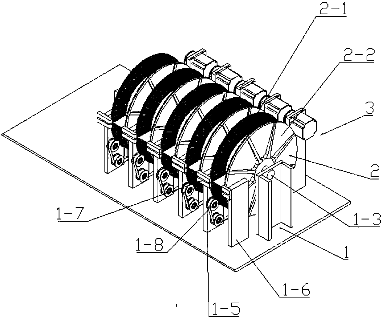
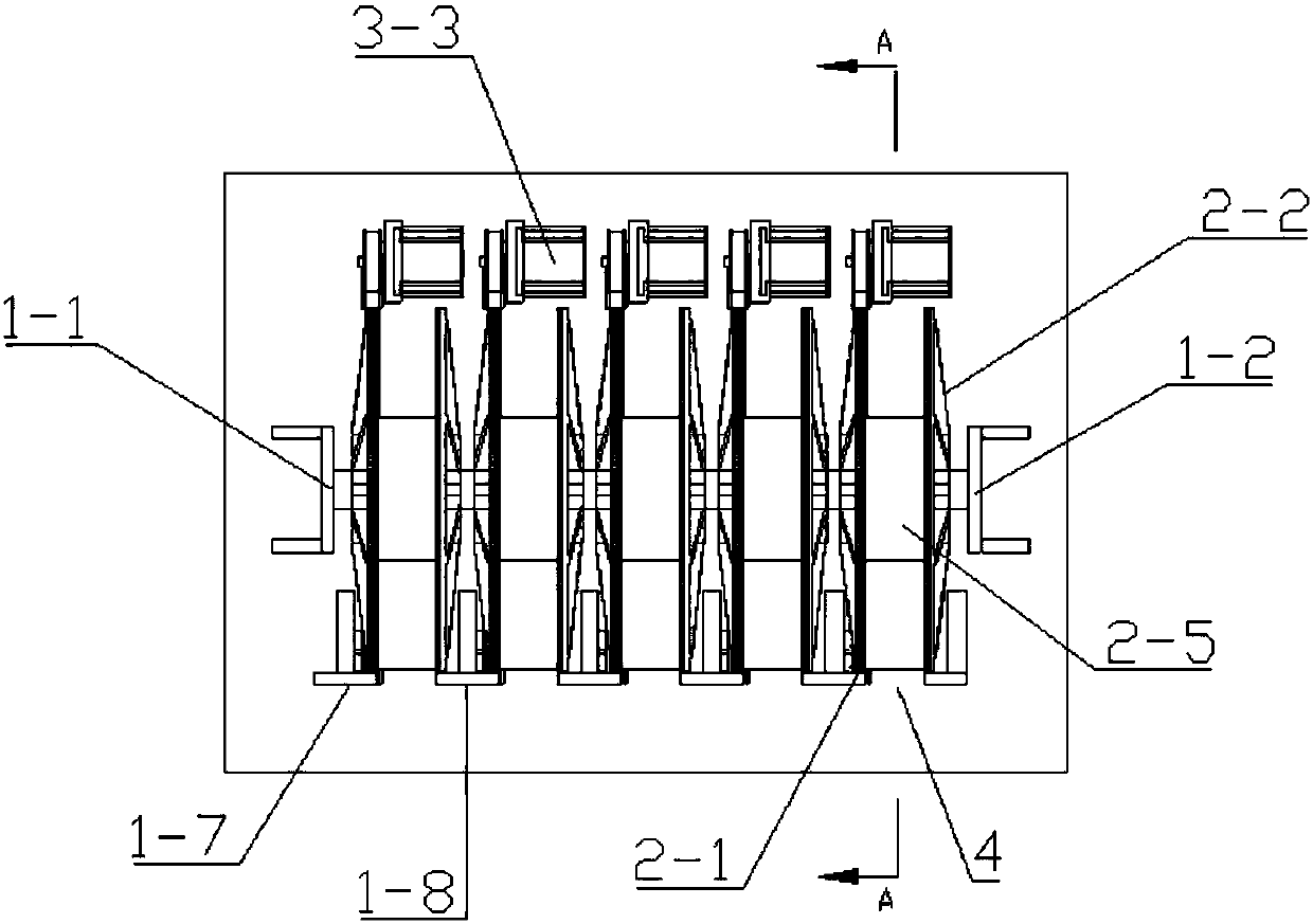
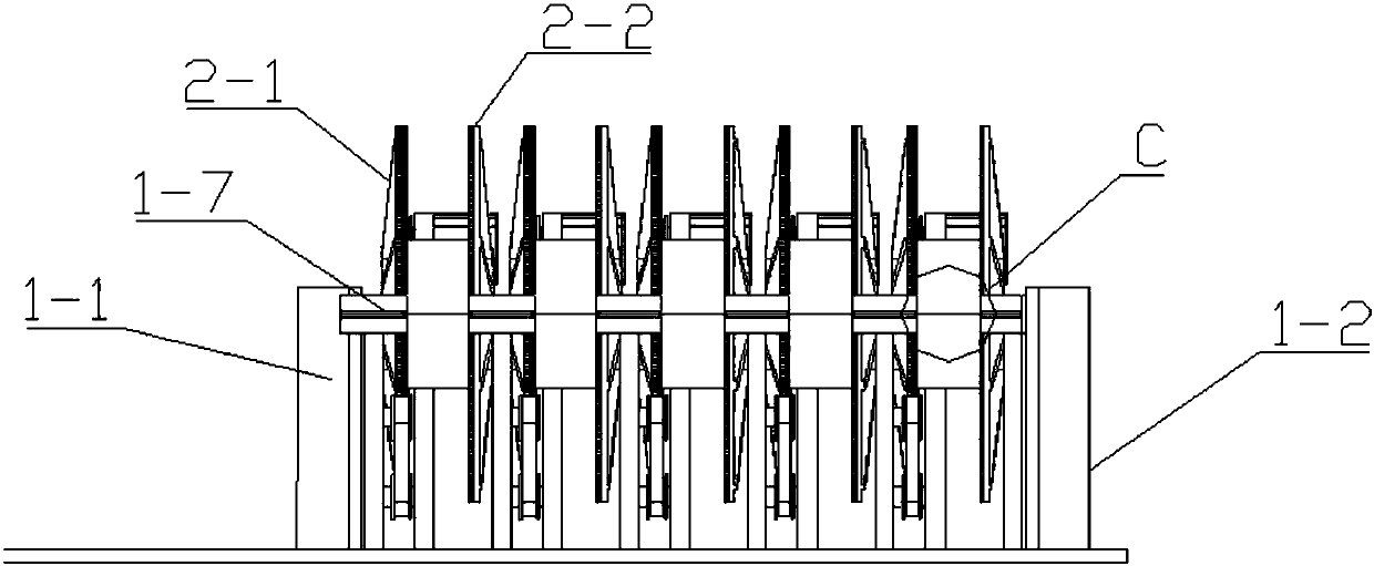
[0038] see Figure 1-Figure 6 A carousel card storage device of the present invention includes a frame 1 and a plurality of card storage mechanisms arranged on the frame 1, wherein each card storage mechanism includes a turntable 2 vertically arranged on the frame 1 and for A turntable drive mechanism 3 that drives the turntable 2 to rotate, wherein, the turntable 2 is equidistantly provided with a plurality of card storage slots 4 for storing cards along the circumferential direction, and the slots of the card storage slots 4 are arranged on the turntable 2; under the turntable 2, there is a supporting member for supporting the cards.

[0039] see Figure 1-Figure 6 , the turntable 2 includes a first turntable body 2-1, a second turntable body 2-2 and a connection mechanism for connecting the first turntable body 2-1 and the second turntable body 2-2, wherein the first The turntable main body 2-1 is equidistantly provided with a plurality of first storage slots 2-3 along th...

Embodiment 2

[0051] see Figure 7-Figure 10The difference between this embodiment and Embodiment 1 is that the extension lines of the first storage tank 2 - 3 and the second storage tank 2 - 4 are staggered from the center of circle of the turntable 2 . Its purpose is, 1. Since the extension lines of the first storage tank 2-3 and the second storage tank 2-4 are staggered from the center of circle of the turntable 2, when the turntable drive mechanism 3 drives the turntable 2 to rotate, The direction of the centrifugal force received by the cards in the card storage slot 4 intersects the length direction of the card storage slot 4, so that the centrifugal force is decomposed into a vertical component force perpendicular to the length direction of the card storage slot 4 and a vertical component force parallel to the length direction of the card storage slot 4. The horizontal component force in the length direction of the card storage slot 4 reduces the centrifugal force. At the same time, ...


PUM


Abstract

The invention discloses a turnplate type card storage device which comprises a rack, turnplates arranged on the rack and a turnplate drive mechanism used for driving the turnplates to rotate. The turnplates are vertically arranged on the rack. A plurality of card storage grooves used for storing cards are formed in the turnplates at equal intervals in the circumferential direction, and groove openings of the card storage grooves are formed in the cylindrical surfaces of the turnplates; and supporting components used for supporting the cards are arranged on the lower portions of the turnplates.The cards stored in the turnplate type card storage device are not prone to shifting under centrifugal force during when rotating as the turnplates rotate; and in addition, the turnplate type card storage device can fully utilize the vertical space, accordingly, the occupied land area is reduced, and arranging and mounting are more convenient.

Description

technical field [0001] The invention relates to a self-service card receiving machine, in particular to a turntable card storage device. Background technique [0002] With the development of society, cards have gradually entered people's lives. Usually after the card processing is completed, it will be sent to each card handling unit. When people need to apply for a card, they can go to the card handling unit to handle the card through manual customer service. The distribution of cards is generally done manually by the staff, which will greatly increase the workload of the staff. Therefore, a self-service card dispenser has appeared on the market. Users only need to fill in their own information on the self-service card dispenser. The card reader will send out the bank card that matches the user's information, thereby reducing the workload of the staff and improving office efficiency. For example, the invention patent application whose application announcement number is CN...

Claims


Application Information

Patent Timeline
Patent Type & Authority Applications(China)
IPC IPC(8): B65D83/08
CPCB65D83/08B65D2583/08
Inventor 王开来吴伟文李南彪徐飞
Owner GUANGZHOU MINGSEN TECH CO LTD
Why Eureka
Try Eureka