Sewing machine

A sewing machine and presser foot lifting technology, applied in the field of sewing equipment, can solve the problems of frequent use of electromagnet-driven presser foot, frequent movement of the ejector rod, and easy damage to the sealing cap, so as to reduce frequent movement, prevent aging and damage, and reduce The effect of the risk of oil spills

Inactive Publication Date: 2018-03-30
JACK SEWING MASCH CO LTD
View PDF6 Cites 12 Cited by
  • Summary
  • Abstract
  • Description
  • Claims
  • Application Information

AI Technical Summary

Problems solved by technology

[0003] As the electromagnet drives the presser foot lifter to be used frequently, the ejector pin moves frequently with the presser foot lifter, so that the sealing cap matched with the ejector pin is easily damaged, resulting in oil leakage

Method used


Image

  • Sewing machine
  • Sewing machine
  • Sewing machine

Examples


Embodiment Construction

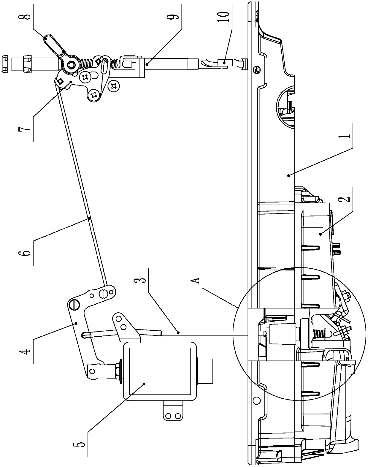
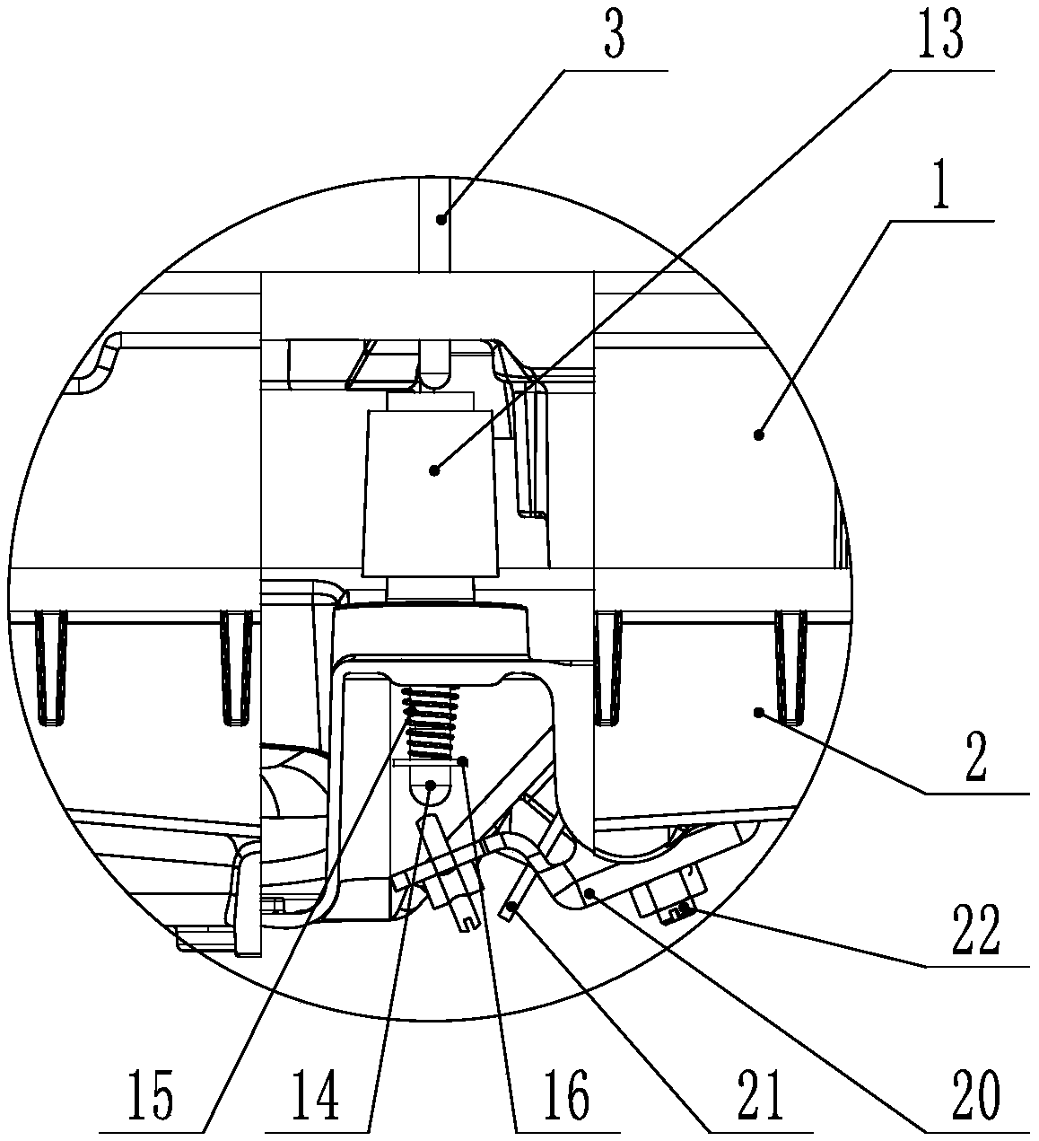
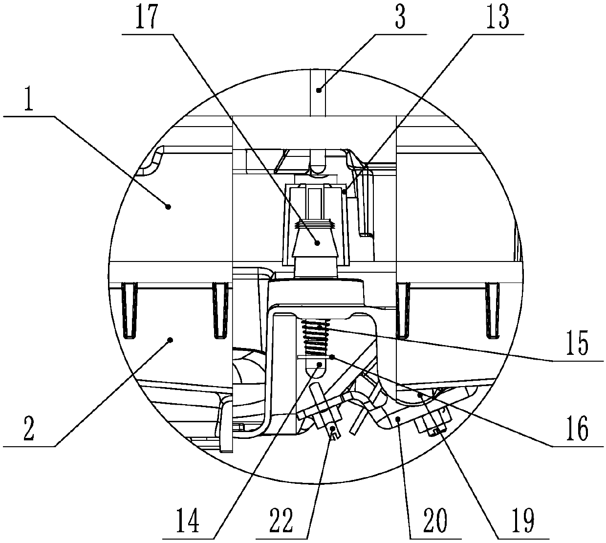
[0023] The present invention will be further described below with specific embodiment, see figure 1 -6:

[0024] A sewing machine, comprising a bottom plate 1, an oil seal plate 2, and a push rod 3, the upper end of the push rod 3 is connected to a presser foot rear lever 4 whose middle part is hinged on the casing, and the rear end of the presser foot rear lever 4 is connected to an electromagnet 5 connection, the front end is connected with the presser foot lifting front lever 7 through the pull rod 6, the presser foot lifting front lever 7 is connected with the presser foot lifting wrench 8 through the presser foot lifting cam, the presser foot lifting front lever 7 is connected through the presser foot lifting plate, the pressing rod guide The frame is connected with a pressing bar 9, and a presser foot 10 is arranged on the pressing bar 9. The action of lifting the presser foot can be driven by the electromagnet 5 and the presser foot lifting wrench 8 . The oil sealing ...


PUM


Abstract

The invention relates to the technical field of sewing equipment, in particular to a sewing machine. The upper end of a top rod is hinged to a lifting presser foot rear lever, the middle of the lifting presser foot rear lever is hinged to a machine shell, the back end of the lifting pressing pedal back lever is connected with an electromagnet, and the front end of the lifting pressing pedal back lever is connected with a lifting pressing pedal front lever through a pull rod; the lifting pressing pedal front lever is connected with a press rod, a boss is arranged in an oil sealing disc, and a through hole which runs through the oil sealing disc is formed in the boss; an oil sealing cap is arranged on the boss, the sealing cap comprises a cap body and a rod part, the lower end of the rod part extends out of the oil sealing disc through the through hole in the boss, and a spring and a limit part are arranged at the lower end of the rod part; one end of the spring abuts against the limit part, the other end of the spring abuts against the bottom plane of the oil sealing disc, and the cap body is connected with a sealing part which is used for preventing the through hole in the boss from leaking oil; the lower end of the top rod penetrates through a baseplate and is located above the oil sealing cap, and the oil sealing cap is driven by a jacking device to move up and down to drivethe top rod to up and down move. According to the sewing machine, frequent movement of the oil sealing cap is reduced, so that the oil sealing cap is not easily aged and damaged, and the risk of oil leakage is reduced.

Description

Technical field: [0001] The technical field of sewing equipment of the present invention particularly refers to a sewing machine. Background technique: [0002] At present, there are many ways to lift the presser foot during use of the lockstitch sewing machine, such as: knee presser foot lifter, electromagnet presser foot lifter and manual presser foot lifter. And usually the above three combinations are all installed on the same sewing machine. Therefore, no matter which driving structure will cause the ejector rod to move during the process of lifting the presser foot, the oil sealing cap between the ejector rod and the oil sealing plate will also produce passive telescopic movement at the same time. [0003] Since the electromagnet is used to drive the presser foot more frequently, the ejector rod moves frequently with the presser foot, so that the sealing cap matched with the ejector rod is easily damaged, resulting in oil leakage. Invention content: [0004] The pu...

Claims


Application Information

Patent Timeline
Patent Type & Authority Applications(China)
IPC IPC(8): D05B29/02D05B71/00
Inventor 丁建明潘建国
Owner JACK SEWING MASCH CO LTD
Why Eureka
Try Eureka