
Oil pocket structure for rolling mill transmission shaft gear joint

A technology of transmission shaft and oil drum, which is applied to the driving device of metal rolling mill, metal rolling, metal rolling, etc., can solve the problems of entering the interlayer, high replacement cost, and delamination of exposed ends, etc. The frequency of replacement, not easy to aging and damage, the effect of saving manpower and material resources

Active Publication Date: 2021-11-12
高科橡塑工业有限公司 +1
View PDF9 Cites 0 Cited by
  • Summary
  • Abstract
  • Description
  • Claims
  • Application Information

AI Technical Summary

Problems solved by technology

The rolling mill generally works continuously, and the emulsion is sprayed outside, and the working environment is relatively complicated
Ordinary protective sleeves are prone to aging and failure, and it is necessary to stop the machine and remove the transmission shaft when replacing, which is time-consuming and laborious, and the replacement cost is high
[0003] At present, the oil bag used in the transmission shaft gear joint of the existing rolling mill adopts a layered structure. After the edges of both ends are connected to the flange, the exposed end is prone to layering, and the external liquid will enter the interlayer, affecting its service life.

Method used


Image

  • Oil pocket structure for rolling mill transmission shaft gear joint
  • Oil pocket structure for rolling mill transmission shaft gear joint
  • Oil pocket structure for rolling mill transmission shaft gear joint

Examples


Embodiment Construction

[0021] In order to make the purpose, technical solutions and advantages of the present invention clearer, the technical solutions in the embodiments of the present invention are clearly and completely described below in conjunction with the accompanying drawings and specific embodiments. Obviously, the described embodiments are only the present invention. Some examples, but not all examples. It should be understood that the specific embodiments described here are only used to explain the present invention, not to limit the present invention.

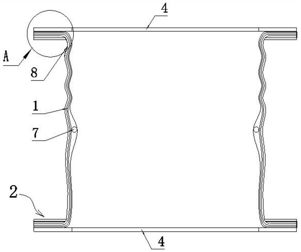
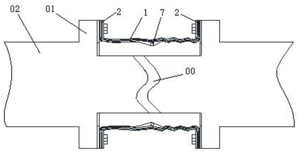
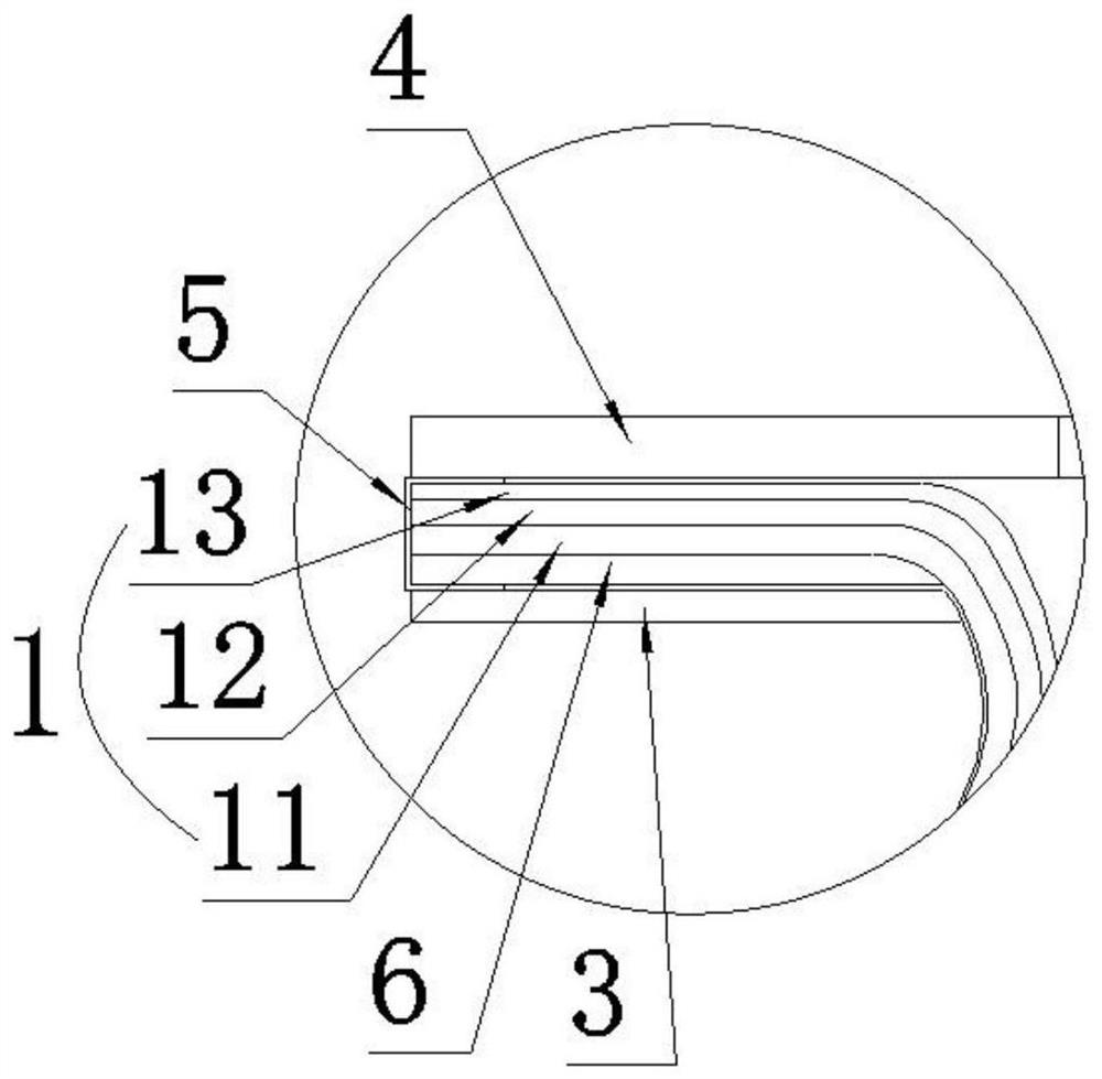
[0022] Such as figure 1 , 2 As shown, the present invention provides an oil bag structure for a gear joint of a rolling mill transmission shaft, comprising a flexible oil bag body 1 of a tubular structure, the oil bag body 1 is wrapped outside the gear joint 00 of a rolling mill transmission shaft, and the oil bag Both ends of the body 1 are respectively provided with flanges 2 for connecting with the flange 01 at the end of the transm...


PUM

PropertyMeasurementUnit
thicknessaaaaaaaaaa
thicknessaaaaaaaaaa
thicknessaaaaaaaaaa

Abstract

The invention discloses an oil pocket structure for a rolling mill transmission shaft gear joint, and belongs to the technical field of metallurgical equipment sealing. The oil pocket structure comprises a flexible oil pocket body of a cylindrical structure, the rolling mill transmission shaft gear joint is wrapped with the oil pocket body, and edge covering structures are arranged on the outer edges of flanging parts at the two ends of the oil pocket body; one side of each edge covering structure abuts against a flange, a first hard gasket is arranged at the other side of each edge covering structure, and through holes connected with the flanges are formed in the flanging parts and the first hard gaskets; and sealing pieces are arranged between the flanging parts and the flanges, so that gaps between the oil pocket body and the flanges can be sealed, and a buffering effect is achieved. The edge covering structures are arranged on the outer edges of the flanging parts, so that external liquid can be prevented from entering the spaces among the layers of the oil pocket body, and the layering phenomenon of the oil pocket body is avoided; and the first hard gaskets at the outer sides of the flanging parts can ensure the flatness of the two ends of the oil pocket body. The oil pocket structure can adapt to complex working conditions and environments, is not easy to age and damage, has excellent flexing resistance, can reduce the replacement frequency, and saves manpower and material resources.

Description

technical field [0001] The invention belongs to the technical field of metallurgical equipment sealing, and in particular relates to an oil bag structure for gear joints of transmission shafts of rolling mills. Background technique [0002] In view of the fact that the medium of the gear joint of the transmission shaft of the rolling mill is gear oil 3200, and the joint has an included angle of 2°, and the rotation speed is 50-688 rpm, there will be a certain torque and tension during work, so it is necessary to install the gear on the transmission shaft of the rolling mill. A protective sleeve is wrapped around the joint to prevent gear oil from leaking out. The rolling mill generally works continuously, and the emulsion is sprayed outside, so the working environment is relatively complicated. Ordinary protective sleeves are prone to aging and failure, and it is necessary to stop the machine and remove the transmission shaft when replacing, which is time-consuming and labo...

Claims


Application Information

Patent Timeline
Patent Type & Authority Applications(China)
IPC IPC(8): B21B35/12
CPCB21B35/12Y02P70/10
Inventor 高文岐何胜通杜喜林张喜俊
Owner 高科橡塑工业有限公司
Learn More