
Cable fixture

A cable fixing device and cable technology, applied in electrical components and other directions, can solve problems such as affecting the internal environment, unorganized cables, affecting maintenance, etc., and achieve the effect of strengthening ventilation, clear wiring, and saving materials

Pending Publication Date: 2018-03-30
重庆华旗线缆有限公司
View PDF0 Cites 2 Cited by
  • Summary
  • Abstract
  • Description
  • Claims
  • Application Information

AI Technical Summary

Problems solved by technology

[0003] Aiming at the deficiencies in the prior art, the present invention provides a cable fixing device, which solves the problem that the cables are not arranged in the traditional cable fixing installation method, and the messy arrangement affects the internal environment and affects the maintenance.

Method used


Image

  • Cable fixture
  • Cable fixture

Examples


Embodiment Construction

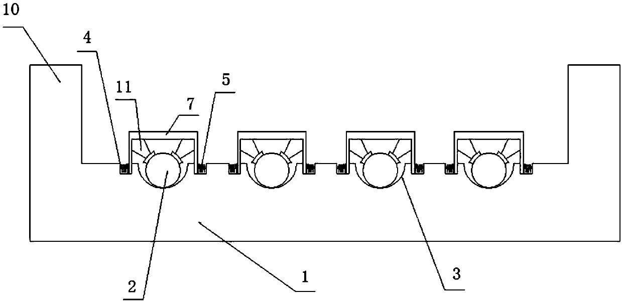
[0019] The present invention will be further described below in conjunction with the accompanying drawings. Such as Figure 1-2 As shown, a cable fixing device includes a base plate 1, support plates 10 are provided at both ends of the base plate 1, and grooves 3 for placing cables 2 are arranged on the base plate 1. In this embodiment, the number of grooves 3 The number is four. Of course, in actual use, the number of grooves 3 is matched with the number of cables arranged in the device.

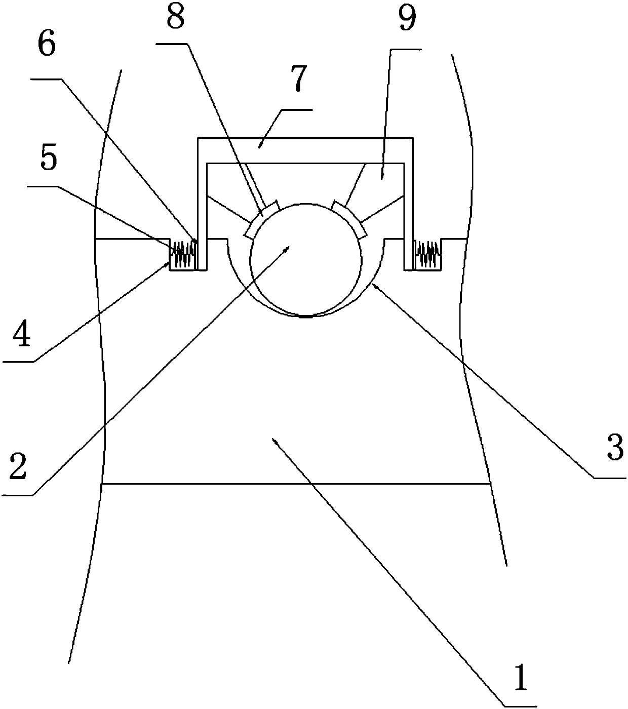
[0020] see figure 2 , the cross-section of the groove 3 is semicircular, the bottom plate 1 on both sides of the groove 3 is divided into a rectangular blind hole 4, and a spring 5 is horizontally arranged in the blind hole 4, and one end of the spring 5 is connected to the blind hole 4 away from On the side of the groove 3, the other end of the spring 5 is connected to the snap-in plate 6, and a fixing piece is provided between the two snap-in plates 6. The fixing piece includes a “ㄇ”-s...


PUM


Abstract

The invention provides a cable fixture, comprising a bottom plate that is provided with grooves for holding cables. The section of each groove is semicircular. The bottom plate is provided with blindholes, which are rectangular, on two sides of each groove. A spring is horizontally arranged in each blind hole. One end of each spring is connected to the side of the corresponding blind hole far away from the corresponding groove, and the other end of each spring is connected with a clamp plate. A fastener is arranged between every two clamp plates in pluggable manner and includes a U-shaped insert; vertical portions of each insert are act on the corresponding clamp plates respectively, each insert is provided with butting parts that function to butt one cable, each butting part comprises acontact sheet that is in inferior arc shape and mates with the cable, and each contact sheet is connected with the corresponding insert through a connection rod. The cable fixture allows cables to bescientifically organized, provides enhanced ventilating and dust-cleaning abilities for the bottom plate, allows the cables to be firmly fixed, enables the cables to be normally used and maintained with good convenience, and has multiple purposes.

Description

technical field [0001] The invention relates to the technical field of cables, in particular to a cable fixing device. Background technique [0002] With the popularization and application of network and electronic component technology, multiple boards are installed in one machine equipment for division of labor and cooperation. Electronic components are installed on the boards, and the electronic components are connected through cables. The existing The installation methods are all directly connected by cables and no longer managed. This will make the cables in the equipment messy and the cables will be intertwined, resulting in no ventilation in the equipment and easy to accumulate dust, affecting the internal environment. It is very inconvenient to distinguish the cables; based on this situation, a new installation method has gradually emerged, which bundles several cables that are relatively close together and arranges them. However, the cables in each bundle are still n...

Claims


Application Information

Patent Timeline
IPC IPC(8): H02G3/02H02G3/03
CPCH02G3/02H02G3/03
Inventor 沈志宗邓帅黄雄波
Owner 重庆华旗线缆有限公司
Features
  • Generate Ideas
  • Intellectual Property
  • Life Sciences
  • Materials
  • Tech Scout
  • Unparalleled Data Quality
  • Higher Quality Content
  • 60% Fewer Hallucinations
Learn More