Differential network communication cable for rail transit vehicle
A technology for rail transit vehicles and differential network, applied in the field of differential network communication cables for rail transit vehicles, can solve the problems of cumbersome, difficult to fix, laborious, etc., and achieve the effect of clear wiring and convenient wiring.
- Summary
- Abstract
- Description
- Claims
- Application Information
AI Technical Summary
Problems solved by technology
Method used
Image

Examples
Embodiment 1
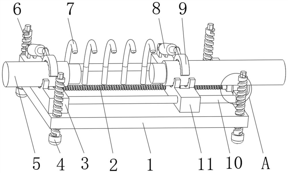
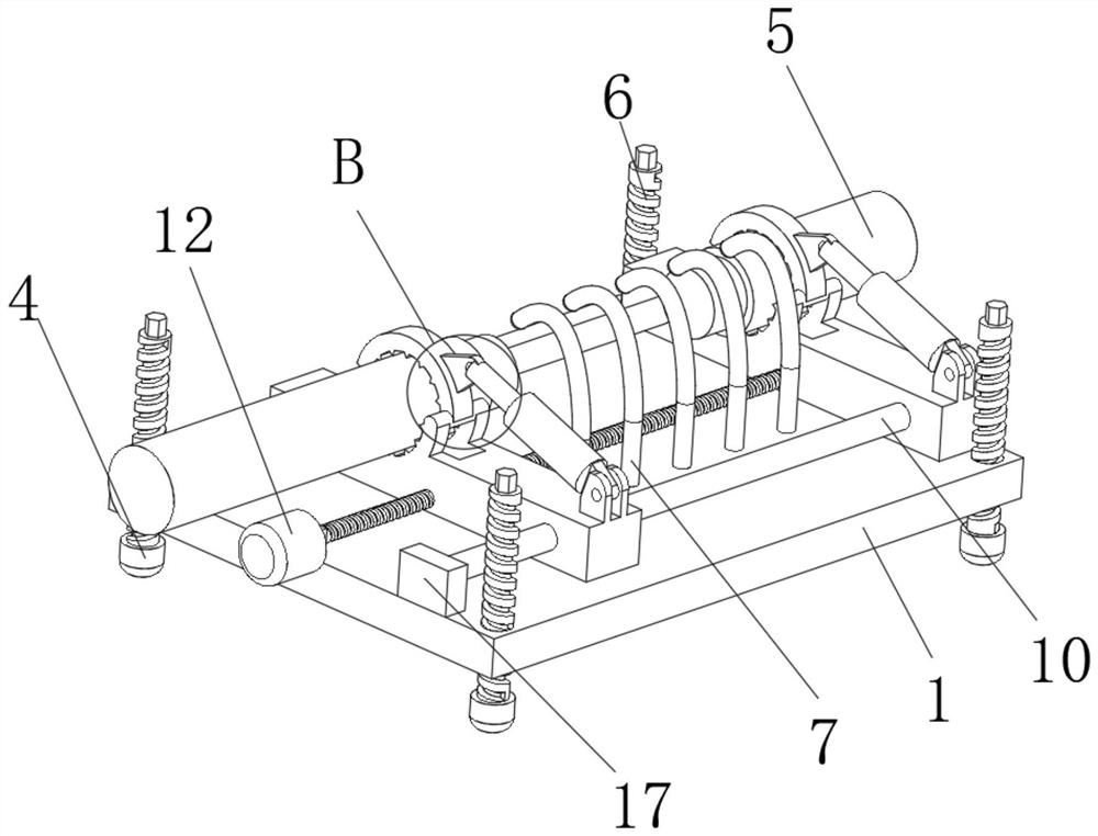
[0036] refer to Figure 1-4 , the present invention provides a differential network communication cable for a rail transit vehicle, comprising a support base 1, the top left side of the support base 1 is fixedly connected with a fixing platform 3, and the top right side of the support base 1 is fixedly connected with a second fixing platform at the front and rear ends. Block 17, fixed stage 3 and second fixed block 17 adjacent side front and rear ends are all fixedly connected with slide bar 10, and the outer periphery of slide bar 10 is slidably connected with mobile stage 11, and the top middle part of fixed stage 3 and mobile stage 11 is all fixed A second clip 15 is connected, and the top side of the second clip 15 is rotatably connected with the first clip 9, and the top side of the first clip 9 is fixedly connected with a connector 16, and the top rear of the fixed table 3 and the mobile table 11 Both are rotatably connected with a hydraulic cylinder 8, and the top of th...
Embodiment 2
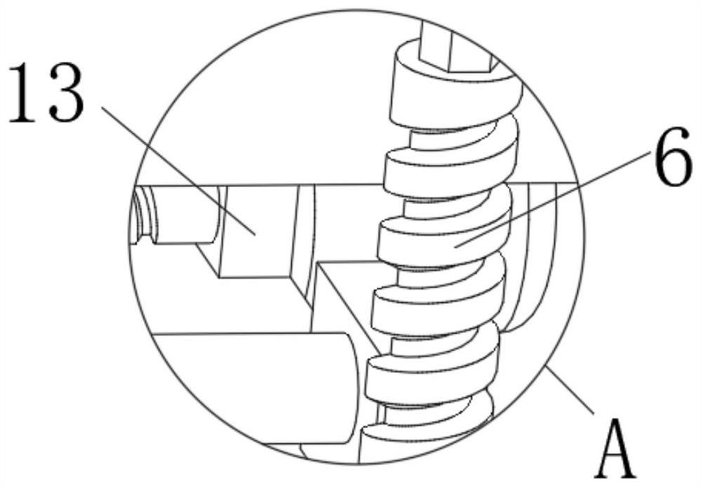
[0039] refer to Figure 1-3 In this embodiment, on the basis of the structural scheme disclosed in the above-mentioned embodiments, threaded rods 6 are threadedly connected to the four corners of the top of the support base 1, and the bottom ends of the threaded rods 6 are rotatably connected to supporting feet 4, and the top ends of the threaded rods 6 All are provided with hexagonal prisms, the material of the supporting feet 4 is rubber and the shape of the supporting feet 4 is hemispherical. When in use, the supporting base 1 is placed under the cable main body 5, and the height of the supporting base 1 is adjusted by rotating the threaded rod 6.
Embodiment 3
[0041] refer to Figure 1-2 In this embodiment, on the basis of the structural scheme disclosed in the above-mentioned embodiments, several light poles 7 are equidistantly fixedly connected to the rear end of the top middle of the support base 1. The light poles 7 are goosenecks and the top ends of the light poles 7 are fixedly connected. There is a light bulb, turn on the light pole 7, and adjust the shape of the light pole 7 so that the top of the light pole 7 can be aligned with the position that needs to be wired, so that the wiring work can be completed more efficiently.
[0042] Working principle: when in use, place the support base 1 under the cable main body 5, and turn the threaded rod 6 to adjust the height of the support base 1. After adjusting to a suitable height, place the cable main body 5 on the second clip 15 and Inside the first clip 9, start the hydraulic cylinder 8 to clamp the cable main body 5, and then start the motor 12 to drive the screw 2 to rotate, a...
PUM
 Abstract
Description
Claims
Application Information
 - R&D
- Intellectual Property
- Life Sciences
- Materials
- Tech Scout
- Unparalleled Data Quality
- Higher Quality Content
- 60% Fewer Hallucinations
Browse by: Latest US Patents, China's latest patents, Technical Efficacy Thesaurus, Application Domain, Technology Topic, Popular Technical Reports.
© 2025 PatSnap. All rights reserved.Legal|Privacy policy|Modern Slavery Act Transparency Statement|Sitemap|About US| Contact US: help@patsnap.com