Pan-tilt structure based on double-parallelogram linkage mechanism

A technology of parallelogram and quadrilateral connecting rod, which is applied in the field of cloud platform structure

Pending Publication Date: 2018-04-03
李海活
View PDF0 Cites 4 Cited by
  • Summary
  • Abstract
  • Description
  • Claims
  • Application Information

AI Technical Summary

Problems solved by technology

However, due to the limitation of the existing gimbal structure technology, the roll axis motors have to be installed at the rear of the shooting equipment, so that the axis direction of the roll axis is blocked by the roll axis motor, and when the shooting equipment is tilted and rotated, the unobstructed range of the lens field of view Less than 180 degrees, not suitable for shooting occasions that require a larger pitch angle

Method used


Image

  • Pan-tilt structure based on double-parallelogram linkage mechanism
  • Pan-tilt structure based on double-parallelogram linkage mechanism

Examples


Embodiment 1

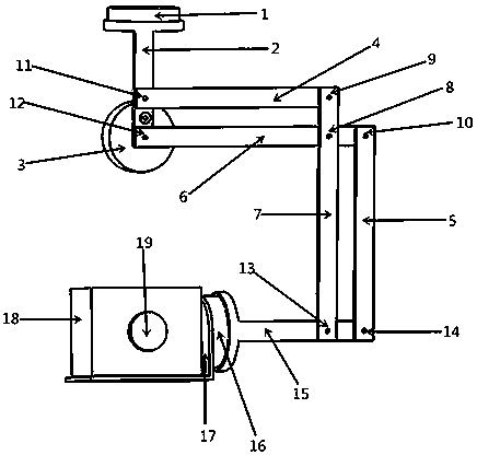
[0018] Example 1: Such as figure 1 As shown, the present invention provides a gimbal structure based on a double parallelogram linkage mechanism, which includes a pan axis motor 1, a pan axis connector 2, a roll axis motor 3, a double parallelogram linkage mechanism, and a pitch axis connector 15. Pitch axis motor 16 and bearing member 17. The photographing equipment mounted on the carrier 17 may be a camera, a video camera, and other photographing devices. In this embodiment, the photographing equipment takes the camera 18 as an example to illustrate the beneficial effects of the present invention. The camera 18 can be fixed to the carrier 17 by a locking member. Of course, it is understandable that the shooting equipment can also be other types of cameras or surveillance cameras, etc. The pan / tilt can be used as an auxiliary device for photography, photography, and monitoring, and can be used in manned aircraft, carriers, automobiles, ships, robots, and movies. Shooting and ...

Embodiment 2

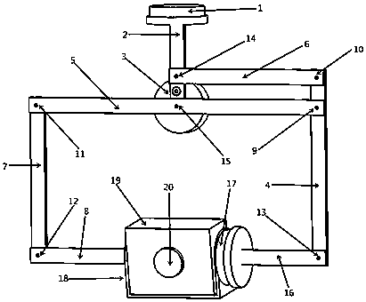
[0024] Example 2: Such as figure 2 As shown, another pan-tilt structure based on a double parallelogram linkage mechanism provided by the present invention includes a pan axis motor 1, a pan axis connector 2, a roll axis motor 3, a double parallelogram linkage mechanism, and a pitch axis connection Piece 16, pitch axis motor 17 and bearing piece 18. The photographing equipment mounted on the carrier 18 may be a camera, a video camera, and other photographing devices. In this embodiment, the photographing equipment takes the camera 19 as an example to illustrate the beneficial effects of the present invention. The camera 19 can be fixed to the carrier 18 by a locking member. Of course, it is understandable that the shooting equipment can also be other types of cameras or surveillance cameras, etc. The pan / tilt can be used as an auxiliary device for photography, photography, and monitoring, and can be used in manned aircraft, carriers, automobiles, ships, robots, and movies. S...


PUM


Abstract

The invention provides a pan-tilt structure capable of achieving pitching shooting vision maximizing of shooting equipment. The pan-tilt structure comprises a heading shaft motor, a heading shaft connecting piece, a transverse roller motor, a double-parallelogram linkage mechanism, a pitching shaft connecting piece and a pitching shaft motor. The heading shaft motor is rotationally connected withthe heading shaft connecting piece. A stator part of the transverse roller motor is fixedly connected with the heading shaft connecting piece. A rotor part of the transverse roller motor is rotationally connected with one connecting rod of the double-parallelogram linkage mechanism. The transverse roller motor rotates to drive the whole double-parallelogram linkage mechanism to move parallelly. One connecting rod of the double-parallelogram linkage mechanism is rotationally connected with the heading shaft connecting piece. The pitching shaft connecting piece is rotationally connected with thedouble-parallelogram linkage mechanism. A rotor part of the pitching shaft motor is rotationally connected with the pitching shaft connecting piece. A stator part of the pitching shaft motor is fixedly connected with a bearing piece for carrying the shooting equipment.

Description

Technical field [0001] The invention relates to the field of photographing equipment, in particular to a pan / tilt structure based on a double parallelogram linkage mechanism. Background technique [0002] The pan / tilt is a carrier mainly used to mount shooting equipment, reduce high-frequency vibration and low-frequency jitter, and obtain stable optical images. However, due to the limitation of the existing PTZ structure and technology, the roll axis motor has to be installed at the rear of the shooting device, so that the axis direction of the roll axis is blocked by the roll axis motor. When the shooting device is tilted and rotated, the lens field of view is unobstructed. Less than 180 degrees, not suitable for shooting situations that require a larger pitch angle. Summary of the invention [0003] In view of this, it is necessary to provide a pan-tilt structure that can maximize the field of view of the shooting device when tilting. [0004] A pan-tilt structure includes a pan...

Claims


Application Information

Patent Timeline
Patent Type & Authority Applications(China)
IPC IPC(8): F16M11/12F16M11/18G03B17/56
CPCG03B17/56F16M11/126F16M11/18
Inventor 李海活
Owner 李海活
Why Eureka
Try Eureka