Air conditioner indoor unit

A technology for air-conditioning indoor units and casings, which is applied in air-conditioning systems, mechanical equipment, space heating and ventilation, etc., and can solve problems such as limited air outlet area and range, low air outlet temperature of air conditioners, and easy air-conditioning diseases , to achieve the effect of improving cooling/heating efficiency and cooling/heating effect, reducing volume and meeting requirements

Active Publication Date: 2018-04-03
QINGDAO HAIER AIR CONDITIONER GENERAL CORP LTD +2
View PDF10 Cites 1 Cited by
  • Summary
  • Abstract
  • Description
  • Claims
  • Application Information

AI Technical Summary

Problems solved by technology

Moreover, since the wind blown out is all the wind after heat exchange, the wind blown out by the indoor unit of this air conditioner is not soft enough.
Especially considering that the air outlet area and range of the lower air outlet are limited, and the air outlet is relatively concentrated. In the cooling mode, the outlet air temperature of the air conditioner is too low, and it will cause extremely uncomfortable feeling when blowing on the user, and it is easy to cause air conditioner diseases.

Method used


Image

  • Air conditioner indoor unit
  • Air conditioner indoor unit
  • Air conditioner indoor unit

Examples


Embodiment Construction

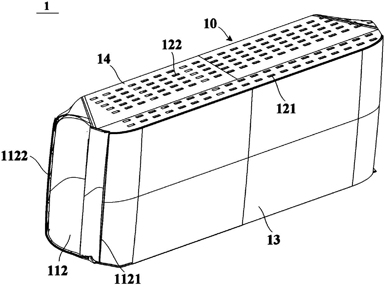
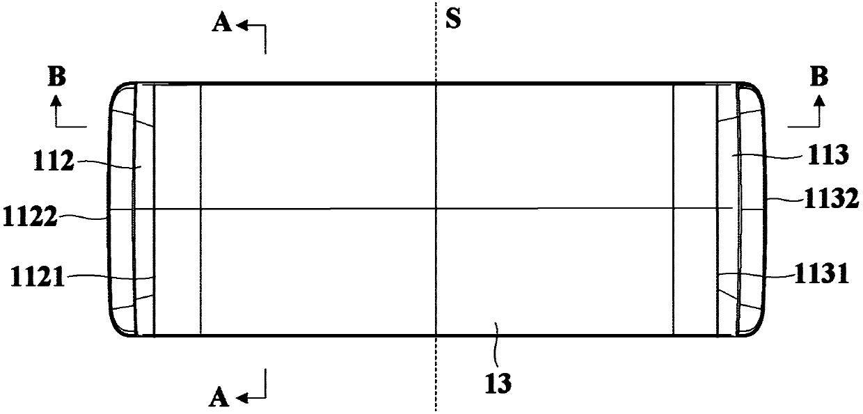
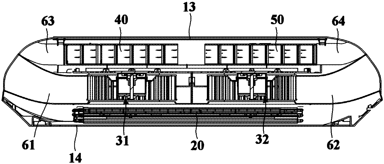
[0049] An embodiment of the present invention provides an air conditioner indoor unit. figure 1 is a schematic structural diagram of an air conditioner indoor unit according to an embodiment of the present invention, figure 2 is a schematic front view of an air conditioner indoor unit according to an embodiment of the present invention, image 3 is along figure 2 A schematic cross-sectional view taken along the section line B-B in, Figure 4 is a schematic exploded view of an air conditioner indoor unit according to an embodiment of the present invention, Figure 5 is along figure 2 A schematic cross-sectional view taken along line A-A in . see Figure 1 to Figure 5 The air conditioner indoor unit 1 of the embodiment of the present invention includes a casing 10, a heat exchange device 20 disposed in the casing 10, a fan assembly 30 disposed on the front side of the heat exchange device 20, and a first ion wind generating device 40 and a second ion wind generating devi...


PUM


Abstract

The invention relates to an air conditioner indoor unit. The air conditioner indoor unit comprises a unit shell, a heat exchanging device, a fan assembly, a first ionic wind generating device and a second ionic wind generating device, the unit shell is provided with a first wind inlet, a second wind inlet, a first side direction wind outlet and a second side direction wind outlet, the first wind inlet and the second wind inlet are located in the upper portion of the unit shell and are front-back arrayed, and the first side direction wind outlet and the second side direction wind outlet are correspondingly located in the two sides of the unit shell; the heat exchanging device is arranged in the unit shell and configured to conduct heat exchanging with air flowing through the heat exchangingdevice, and the fan assembly is arranged on the front side of the heat exchanging device and is configured to promote natural air entering from the second wind inlet to flow towards the heat exchanging device and promote heat exchanging air after being subjected to heat exchanging through the heat exchanging device to flow towards the first side direction wind outlet and the second side directionwind outlet; and the first ionic wind generating device and the second ionic wind generating device are arranged on the front side of the fan assembly side by side in the transverse direction and areconfigured to promote natural air entered from the first wind inlet to directly flow towards the first side direction wind outlet and the second side direction wind outlet, so that the natural air and the heat exchanging air after being subjected to heat exchanging through the heat exchanging device are mixed at the first side direction wind outlet and the second side direction wind outlet.

Description

technical field [0001] The invention relates to air-conditioning technology, in particular to an air-conditioning indoor unit. Background technique [0002] Generally, the air outlet mode of the indoor unit of the wall-mounted air conditioner is mostly downward air outlet, and the air sent by this air supply method will directly blow to the human body. And, because all the wind blown out is the wind after heat exchange, the wind blown out by this air-conditioning indoor unit is not soft enough. Especially considering that the air outlet area and range of the lower air outlet are limited, and the air outlet is relatively concentrated. In the cooling mode, the outlet air temperature of the air conditioner is too low, and it will cause extreme discomfort to the user when it is blown on the body, and it is easy to cause air conditioner disease. Therefore, on the premise of meeting the requirements of indoor cooling capacity and cooling efficiency, how to expand the air supply r...

Claims


Application Information

Patent Timeline
IPC IPC(8): F24F1/00F24F3/16F24F13/08F24F13/20F24F13/24F24F13/30
CPCF24F1/0014F24F1/0022F24F1/0059F24F13/08F24F13/20F24F13/24F24F13/30F24F2013/247F24F8/192F24F8/30
Inventor 李健王永涛
Owner QINGDAO HAIER AIR CONDITIONER GENERAL CORP LTD
Why Eureka
Try Eureka