Low-voltage busbar clamp

A confluence busbar and low-voltage technology, applied in the field of power access devices, to avoid short-circuit faults and solve the effect of access reliability

Pending Publication Date: 2018-04-03
XUZHOU HANDLER SPECIAL VEHICLE
View PDF6 Cites 1 Cited by
  • Summary
  • Abstract
  • Description
  • Claims
  • Application Information

AI Technical Summary

Problems solved by technology

[0006] In view of the above problems, the present invention provides a low-voltage confluence busbar clip, which solves the problem that the emergency support equipment cables are connected to the busbar in the low-voltage power distribution cabinet in the charged state

Method used


Image

  • Low-voltage busbar clamp
  • Low-voltage busbar clamp
  • Low-voltage busbar clamp

Examples


Embodiment 1

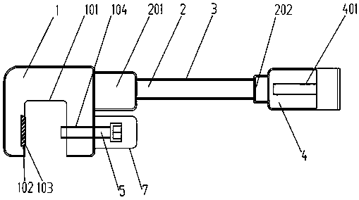
[0035] Such as figure 1 As shown, it is a schematic structural diagram of the low-voltage busbar clamp provided in this embodiment, including a busbar fixture 1, a busbar 2, and a connecting seat 4. One end of the busbar 2 is connected to the busbar fixture 1, and the other end is connected to the connecting seat 4. . A U-shaped groove 101 is formed on the busbar fixture 1, and a trapezoidal notch 102 is provided on the front surface of the U-shaped notch 101, and a conductive spring piece 103 is embedded in the trapezoidal notch 102. The lower end of the U-shaped groove 101 is provided with a threaded hole 104 through which the fastening bolt 5 is connected to the busbar fixture 1 . Insulation sheath 3 is wrapped around busbar fixture 1, bus bar 2, and connection seat 4; connection port is provided on connection seat 4, and internal thread 401 is provided in connection seat 4 in this embodiment to realize Better to connect with the crimp terminal at one end of the cable.

...

Embodiment 2

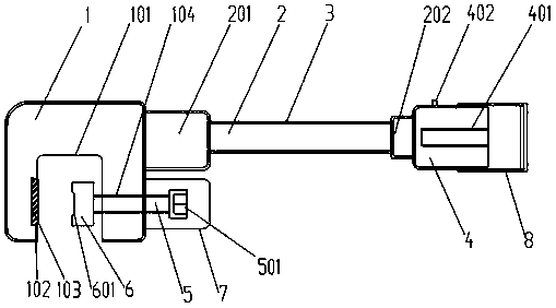
[0039] This embodiment is an improvement on the basis of Embodiment 1, as figure 2 As shown, the internal thread 401 set in the connection seat 4 can be connected with the external cable connection terminal or the cable quick connector seat through a stud, and the connection seat 4 is provided with a live indicator light 402. When the low-voltage busbar is charged, the charged Indicator light 402 will work. In order to prevent dust, debris, etc. from entering the connection base 4 , a connection base dust cover 8 is assembled outside the connection base 4 .

[0040] In order to prevent electric shock during operation, an insulating sheath 3 is wrapped around the outside of the busbar fixture 1, busbar 2, and connecting seat 4, and the insulating sheath 3 outside the connecting seat 4 can be turned over to the confluence when connecting cables. on pole 2. After the cable is connected, the cable can be wrapped again to realize the function of opening and closing, which improv...

Embodiment 3

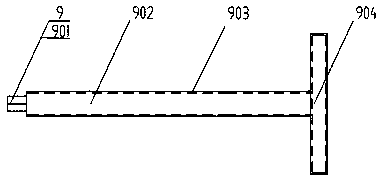
[0043] This embodiment is another improvement on the basis of Embodiment 1. In order to adapt to different forms of busbars, the types of busbars can be made into various types, such as figure 2 right-angled version shown. In addition, in order to meet the requirements of carrying large current, the number of connection sockets can also be multiple, such as Figure 4 As shown, each connection seat is connected to the bus bar through the bus strut.

[0044] When using the low-voltage busbar clamp provided by the present invention, firstly, the terminal at one end of the cable is reliably connected to the low-voltage busbar clamp through the connection seat, and then the low-voltage busbar clamp is placed on the low-voltage busbar, and the busbar is inserted through the slot. The busbar is snapped in, and the fastening bolt is rotated through the tightening rod until the busbar fixture is reliably connected to the low-voltage busbar. Since the low-voltage busbar clips are all...


PUM


Abstract

The invention discloses a low-voltage busbar clamp. The low-voltage busbar clamp comprises a bus rod; a busbar clamp is arranged at one end of the bus rod while connecting bases are arranged at the other end, wherein the busbar clamp comprises a clamping groove for clamping a busbar; a fastening part for fastening the clamped busbar is arranged in the clamping groove; a connecting port is formed in each connecting base; and an insulating protection layer is arranged on the outer surfaces of the busbar clamp, the bus rod, the connecting bases and the fastening part. By virtue of the low-voltagebusbar clamp provided by the invention, the low-voltage busbar clamp and a busbar in a low-voltage power distribution cabinet can be connected conveniently, and by virtue of the fastening part, stable and reliable connection and fixation can be realized; and by virtue of the connecting bases, a cable and the like, the emergency safeguarding equipment cable can be connected to the busbar in the low-voltage power distribution cabinet in an electrified state.

Description

technical field [0001] The invention relates to a power access device, in particular to a low-voltage bus bar clip. Background technique [0002] At present, the requirements for power reliability are getting higher and higher. In order to ensure that users do not have power outages, emergency power protection, power transmission, temporary power supply, and power supply are becoming more and more common. The use of emergency equipment for power supply or power supply is used to ensure user demand for electricity. has become the norm. [0003] At present, for the emergency power supply or power taking operation of 0.4kV users, the connecting cables of the emergency equipment are connected to the low-voltage power distribution cabinet of the user, and the power is supplied to the user or the power is transferred to another user through the emergency equipment. At present, my country's distribution network The low-voltage power distribution cabinet used is a standard power dis...

Claims


Application Information

Patent Timeline
Patent Type & Authority Applications(China)
IPC IPC(8): H02B1/20
CPCH02B1/20
Inventor 陈允柯胡德敏朱丽赵继泉袁玉柱王衡郭维于百业
Owner XUZHOU HANDLER SPECIAL VEHICLE
Why Eureka
Try Eureka