
Static contact and switching device

A technology of switch devices and static contacts, applied in the direction of electric switches, circuit breaker contacts, electrical components, etc., can solve the problems of large arc influence, limited current limiting effect, indirect current limiting effect, etc., and achieve direct current limiting , Improve the resistance and reduce the effect of arc energy

Pending Publication Date: 2021-11-30
STATE GRID FUJIAN ELECTRIC POWER CO LTD +2
View PDF7 Cites 0 Cited by
  • Summary
  • Abstract
  • Description
  • Claims
  • Application Information

AI Technical Summary

Problems solved by technology

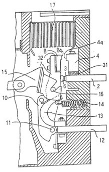
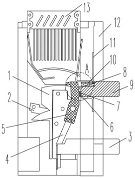
like figure 1 As shown, an air circuit breaker proposed by Patent No. 02804534.3 uses the second circuit to limit the current when the current is turned on or off, but it uses a resistance alloy or steel plate to weld the contacts together, because the contact area is large For example, when using high-resistance materials such as iron-chromium-aluminum, the copper-based contacts will be melted due to the high temperature rise caused by the high resistance, so only medium-resistance materials can be used, and there is a problem of limited current limiting effect ;like figure 2 As shown, a contact device and a circuit breaker proposed in Patent No. 201220410921.1, which indirectly form a new conductive current-limiting circuit through the arc, which is greatly affected by the arc, may have failures, and the current-limiting effect is not direct. In addition, the above The two existing technologies are only applicable to snap-in rotary contacts, and cannot be applied to reversible rotary plug-in contacts

Method used


Image

  • Static contact and switching device
  • Static contact and switching device
  • Static contact and switching device

Examples


Embodiment Construction

[0036] Features and exemplary embodiments of various aspects of the invention will be described in detail below. In the following detailed description, numerous specific details are set forth in order to provide a thorough understanding of the present invention. It will be apparent, however, to one skilled in the art that the present invention may be practiced without some of these specific details. The following description of the embodiments is only to provide a better understanding of the present invention by showing examples of the present invention. The present invention is by no means limited to any specific configuration set forth below, but covers any modification, substitution and improvement of elements, components without departing from the spirit of the invention. In the drawings and the following description, well-known structures and techniques have not been shown in order to avoid unnecessarily obscuring the present invention.

[0037] For the convenience of d...


PUM


Abstract

The invention discloses a static contact and a switching device using the static contact. The switching device comprises an insulating shell, a power supply wiring end, a moving contact and static contacts; the static contacts comprise a first static contact and a second static contact, wherein the second static contact is arranged on one side of the first static contact in the width direction of the switching device, and the resistor body is electrically connected with a power supply terminal of the switch device. According to the invention, the other high-resistance circuit is arranged in parallel with the low-resistance circuit, the low-resistance circuit bears normal working current, and the high-resistance circuit reduces the current when the current is broken to generate an arc, so that the arc energy is reduced, and the contact is protected to the greatest extent.

Description

technical field [0001] The invention relates to the field of low-voltage electrical appliances, in particular to a static contact and a switch device. Background technique [0002] In the low-voltage electrical appliance industry, due to the presence of resistive loads, inductive loads, capacitive loads, and mixed loads, when each load is started or cut off, there is an inrush current greater than the rated current. Terminal appliances or power distribution appliances bring overload impacts of several times the rated current. For example, when the load is faulty and short-circuited, it will bring dozens of times the impact of short-circuit current to terminal appliances or power distribution appliances. Both overload current impact and short-circuit current impact will cause arcing, and the arc will burn or weld the copper-based contacts carrying the current, making the line unable to be connected or cut off, resulting in electrical accidents; for this reason, in the design ...

Claims


Application Information

Patent Timeline
Patent Type & Authority Applications(China)
IPC IPC(8): H01H73/04H01H9/42H01H9/38
CPCH01H73/04H01H9/42H01H9/38
Inventor 李怡然陈石川林团南寅沈迪王文涛任庆庆刘万里周健张晓璟李超苏文冉高会强贾薪淼
Owner STATE GRID FUJIAN ELECTRIC POWER CO LTD
Learn More