Walking tensioning arm structure

A tensioning arm and tensioning plate technology, applied in the field of rotary tillers, can solve the problems of difficult installation and positioning, complex structure of the walking tensioning arm, and large space required for installation, and achieves simple structure, fast and reliable positioning and connection, accurate The effect of positioning links

Inactive Publication Date: 2018-04-06
WUXI SONGTIANBAO MACHINERY TECH CO LTD
View PDF0 Cites 0 Cited by
  • Summary
  • Abstract
  • Description
  • Claims
  • Application Information

AI Technical Summary

Problems solved by technology

[0002] The rotary tiller is a commonly used agricultural machinery, which is pulled by a light crawler tractor. The working part of the light crawler tractor is at the rear of the light crawler tractor. The walking tension arm structure is an important part of the rotary tiller. The existing walking tension The arm structure is complex, resulting in the problem of requiring a large space during installation
In addition, the installation and positioning of the existing walking arm structure is relatively difficult

Method used


Image

  • Walking tensioning arm structure
  • Walking tensioning arm structure

Examples


Embodiment Construction

[0014] The specific embodiments of the present invention will be further described below in conjunction with the accompanying drawings.

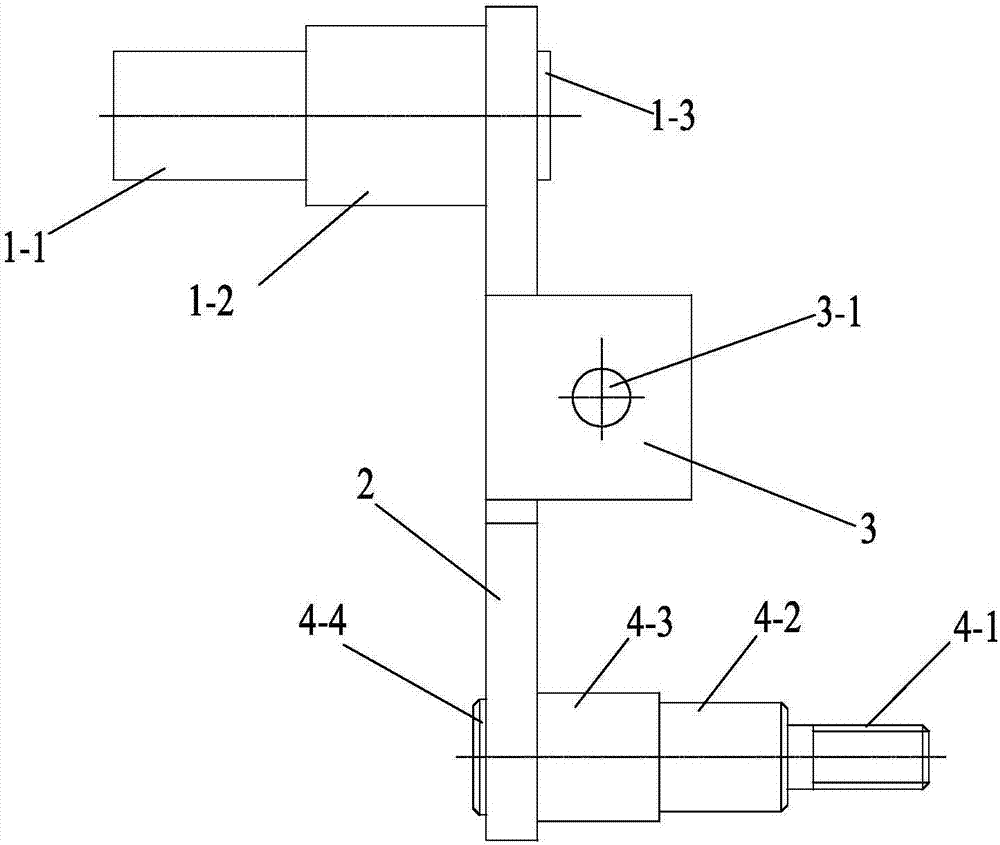
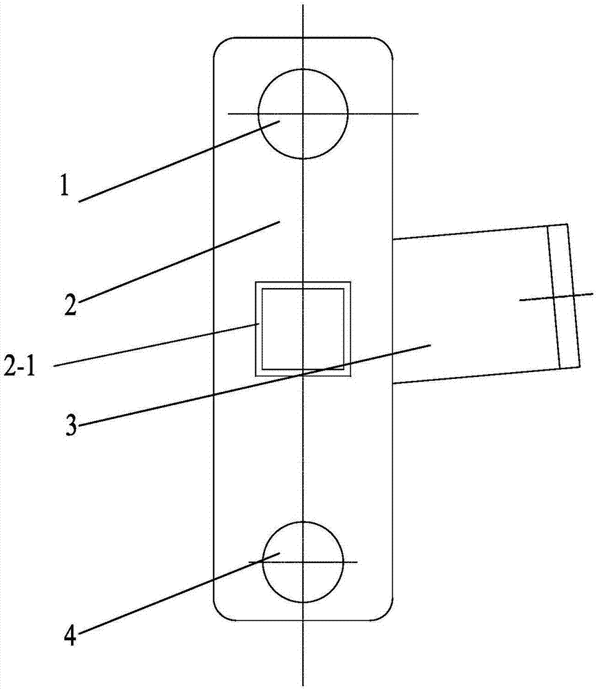
[0015] figure 1 , 2 Among them, including the tensioning wheel shaft 1, the first shaft part 1-1 of the tensioning wheel shaft, the second shaft part 1-2 of the tensioning wheel shaft, the tensioning arm 2, the return-shaped groove 2-1, the tensioning plate 3, and the connecting hole 3 -1. Connecting seat shaft 4, connecting seat shaft first shaft part 4-1, connecting seat shaft second shaft part 4-2, connecting seat shaft third shaft part 4-3, connecting seat shaft connecting part 4-4, etc. .

[0016] Such as figure 1 , 2 As shown, the present invention is a walking tension arm structure, including a tension arm 2, the tension wheel shaft 1 is fixed on one side surface of the upper part of the tension arm 2, and the connection seat shaft 4 is fixed on the other side surface of the bottom part of the tension arm 2 , the middle part of t...


PUM


Abstract

The invention belongs to the technical field of rotary tillers, and relates to a walking tensioning arm structure, including a tensioning arm, the surface of one side of the upper part of the tensioning arm is fixed with a tensioning wheel shaft, and the surface of the other side of the lower part of the tensioning arm is fixedly connected with a seat shaft. A tensioning plate is fixed at the middle part of the tensioning arm; the tensioning wheel shaft has a first shaft portion of the tensioning wheel shaft and a second shaft portion of the tensioning wheel shaft, and the diameter of the first shaft portion of the first tensioning wheel shaft is smaller than that of the second tensioning wheel shaft. The diameter of the second shaft part of the tension wheel shaft, the connecting seat shaft has the first shaft part of the connecting seat shaft, the second shaft part of the connecting seat shaft, and the third shaft part of the connecting seat shaft, wherein the first shaft part of the connecting seat shaft is a threaded shaft, and the connection The second shaft part of the seat shaft and the third shaft part connected to the seat shaft are optical axes. The structure is convenient and quick to install, and the action is reliable and stable during use.

Description

technical field [0001] The invention belongs to the technical field of rotary tillers, and relates to a walking tension arm structure. Background technique [0002] The rotary tiller is a commonly used agricultural machinery, which is pulled by a light crawler tractor. The working part of the light crawler tractor is at the rear of the light crawler tractor. The walking tension arm structure is an important part of the rotary tiller. The existing walking tension The arm structure is complicated, resulting in a problem that a large space is required during installation. In addition, it is relatively difficult to install and locate the existing walking arm structure. Contents of the invention [0003] Aiming at the above problems, the present invention provides a walking tension arm structure, which is convenient and quick to install and reliable and stable in operation. [0004] According to the technical solution of the present invention: a walking tension arm structure,...

Claims


Application Information

Patent Timeline
Patent Type & Authority Applications(China)
IPC IPC(8): F16H7/08A01B35/20
CPCF16H7/08A01B35/20
Inventor 徐浩石亮
Owner WUXI SONGTIANBAO MACHINERY TECH CO LTD
Why Eureka
Try Eureka