High-reliability rectifier bridge device

A rectifier bridge stack, reliability technology, applied in the direction of electric solid devices, semiconductor devices, semiconductor/solid state device components, etc., can solve the problems of device damage, large heat generation of end products, unfavorable energy saving and environmental protection, etc., to improve the installation accuracy Effect

Active Publication Date: 2018-04-06
SUZHOU GOODARK ELECTRONICS CO LTD
View PDF5 Cites 2 Cited by
  • Summary
  • Abstract
  • Description
  • Claims
  • Application Information

AI Technical Summary

Problems solved by technology

To sum up, the existing technology has the disadvantages that the product has a large thickness and takes up a large space on the PCB board, which is not suitable for the miniaturization of the terminal product; the heat dissipation performance of the product is not good, resulting in a large heat generation of the terminal product, which is not conducive to energy saving and environmental protection; the reflow soldering method is not suitable Soldering, when other products on the PCB board need to be soldered by reflow soldering, the entire PCB board needs to be heated twice, which will cause technical problems such as damage to the assembled devices

Method used


Image

  • High-reliability rectifier bridge device
  • High-reliability rectifier bridge device
  • High-reliability rectifier bridge device

Examples


Embodiment

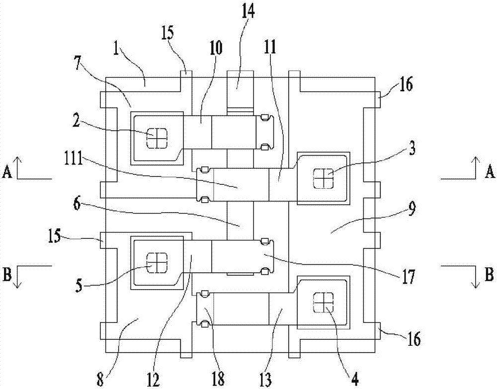
[0025] Embodiment: A high-reliability rectifier bridge stack device, including: first, second, third, fourth diode chips 2, 3, 4, 5 and negative metal strips covered by epoxy package 1 6. First and second metal substrates 7, 8 and E-shaped metal substrates 9 are respectively fixed on the bottom of the epoxy package 1 and on the left and right sides, and the negative electrode metal strip 6 is located on the first and second Between the metal substrates 7, 8 and the E-shaped metal substrate 9;

[0026] The positive terminal of the first diode chip 2 is electrically connected with the upper surface of the first metal substrate 7, the negative terminal of the second diode chip 3 is electrically connected with the upper surface of one end of the E-shaped metal substrate 9, and the third diode The negative end of the chip 4 is electrically connected to the upper surface of the other end of the E-shaped metal substrate 9, and the positive end of the fourth diode chip 5 is electrical...


PUM


Abstract

The invention relates to a high-reliability rectifier bridge device. The device comprises a first diode chip, a second diode chip, a third diode chip, a fourth diode chip and a negative pole metal strip which are wrapped by an epoxy packaging body; a first connecting sheet, a second connecting sheet, a third connecting sheet and a fourth connecting sheet are parallelly disposed in a front-rear direction; the front end of the negative pole metal strip, which is located between a first metal substrate and an E-shaped metal substrate, is provided with a bent portion; the bottom of the bent portion and the bottoms of the first metal substrate, a second first metal substrate and the E-shaped metal substrate are located on the same horizontal plane and all protrude out of the epoxy packaging body; the first metal substrate and the second metal substrate serve as alternating current input ends; the bent portion of the negative pole metal strips serves as a direct-current negative pole end; and the E-shaped metal substrate serves as a direct-current positive pole end. According to the high-reliability rectifier bridge device of the invention, a heat dissipation path between a chip and a PCB is the shortest; being made of a metal material, the heat dissipation sheets have optimal heat conductivity; and the heat dissipation capability of the PCB itself is fully utilized.

Description

technical field [0001] The invention relates to a rectifying semiconductor device, in particular to a rectifying bridge stack device with high reliability. Background technique [0002] The rectifier is a bridge structure composed of four rectifying diodes. It uses the unidirectional conduction characteristics of the diodes to rectify the alternating current. Since the utilization efficiency of the bridge rectifier for the input sine wave is twice as high as that of the wave rectification, it is half of the diode. It is a significant improvement of wave rectification, so it is widely used in circuits that convert alternating current into direct current. [0003] On the one hand, the existing double-row laminated structure rectifier has a simple production process and is easy to operate. However, the flatness of the support sheet where each diode grain is located affects each other, resulting in unstable internal stress conditions during the production process, and damage to...

Claims


Application Information

Patent Timeline
Patent Type & Authority Applications(China)
IPC IPC(8): H01L23/367H01L23/373H01L23/467H01L23/492H01L25/07
CPCH01L23/3114H01L23/3121H01L23/49503H01L23/49575H01L25/072H01L23/367H01L23/3736H01L23/492H01L23/3677H01L23/467H01L2224/40095H01L2224/40245H01L2924/181H01L24/40H01L23/31H01L25/07H01L2924/00014H01L2924/00012H01L2224/37099H01L2224/84
Inventor 何洪运程琳刘玉龙
Owner SUZHOU GOODARK ELECTRONICS CO LTD
Why Eureka
Try Eureka