[0019] now refer to Figure 1 to Figure 4 The present invention is described in detail. It should be understood that the following descriptions are only examples of the present invention and do not constitute any limitation to the present invention. Various embodiments can be combined with each other to form other embodiments not described below or shown in the drawings.
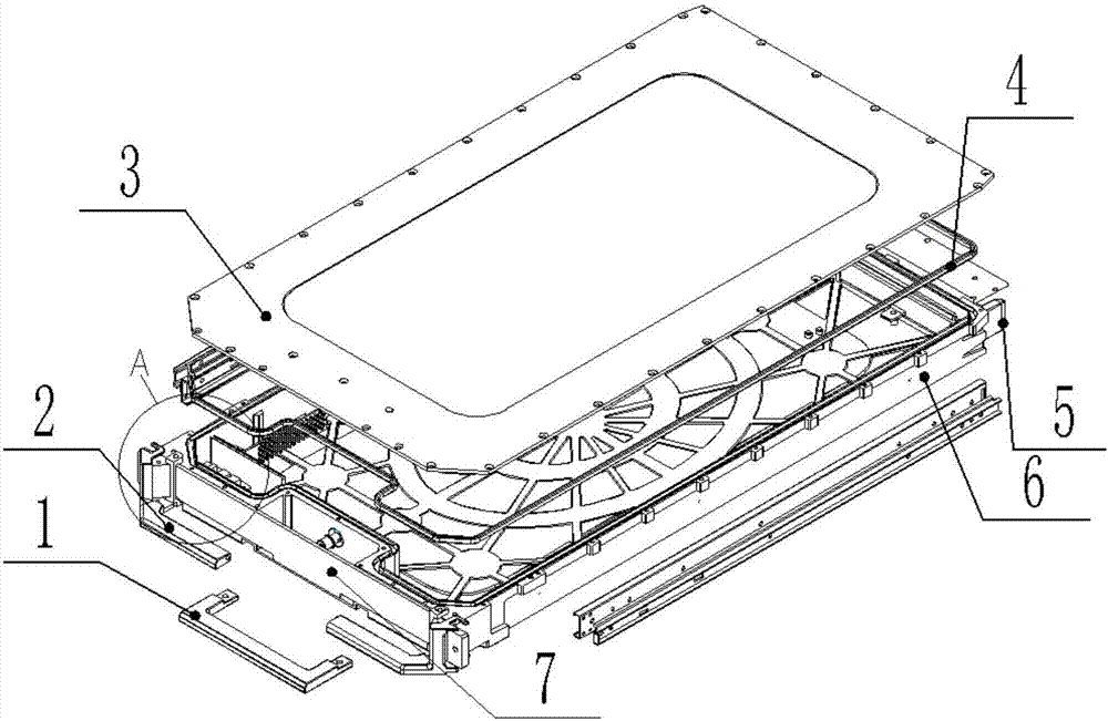
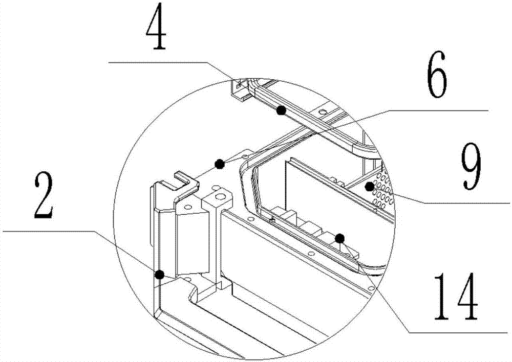
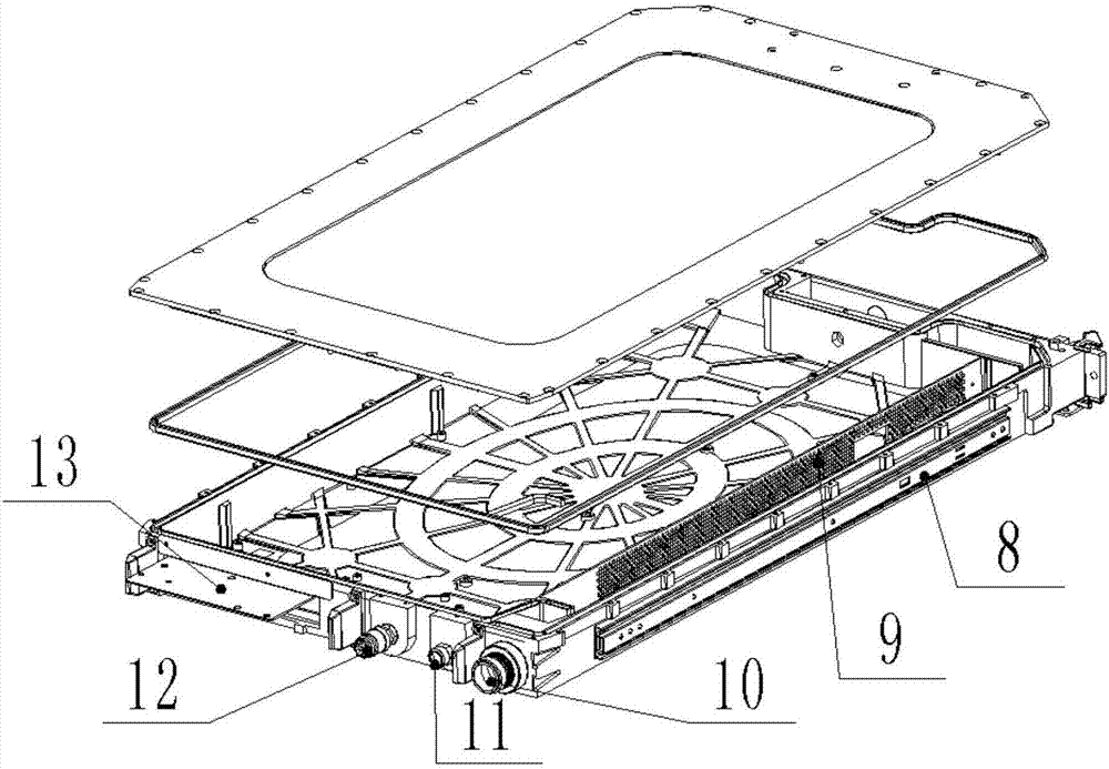
[0020] refer to Figure 1 to Figure 4 , according to one embodiment of the present invention, a casing structure for a fully enclosed blade server is provided, including: a casing 6 including a front end, a rear end, and opposite side walls connecting the front end and the rear end ; The air outlet valve 10 and the liquid inlet valve 12 are respectively arranged at the rear end; and the pressure regulating valve 11 and the liquid level sensor module 14, the pressure regulating valve 11 is arranged at the rear end, and the liquid level sensor module 14 is arranged in the housing 6 And it is electrically connected with the pressure regulating valve 11 to drive the pressure regulating valve 11 to open or close. In one embodiment of the present invention, the air outlet valve 10, the liquid inlet valve 12, and the pressure regulating valve 11 further include a male head arranged on the casing 6 and a female head arranged on the server box. In actual operation, through Connect the respective male and female heads to each other for use.
[0021] In one embodiment of the present invention, the inside of the casing structure is filled with cold liquid through the liquid inlet valve 12 . In one embodiment of the present invention, the liquid level sensor module 14 is electrically communicated with the liquid inlet valve 12, and when the liquid level sensor module 14 senses that the charged cold liquid has reached Liquid has been charged), then control the liquid inlet valve 12 to close. In other embodiments of the present invention, of course, other control methods and components can also be used to control the amount of cold liquid that the liquid inlet valve 12 fills into the casing structure.
[0022] In use, when the cold liquid undergoes a phase change (that is, boils) due to the heat generated by the heating element immersed in it, the generated gas can be discharged from the casing 6 through the gas outlet valve 10; further, as mentioned above, the gas outlet valve 10 includes a male head set on the housing 6 and a female head set on the server box, the gas generated at this time can be discharged out of the blade server through the male head and female head structure of the air outlet valve 10 which is connected (communicated) .
[0023] Further, in one embodiment of the present invention, when encountering an accident such as power failure or damage to the gas outlet valve 10, in order to prevent the heat of the heating element immersed in the cold liquid that has not stopped working at this time from causing the generated gas to fail To discharge in time, the liquid level sensor module 14 is arranged in the casing 6 and electrically connected with the pressure regulating valve 11 to drive the pressure regulating valve 11 to open or close. More specifically, when encountering an accident such as power failure or damage to the air outlet valve 10, the inside of the casing structure is completely sealed at this time, and the heat of the heating element causes the generated gas to have a larger volume than the cold liquid. If it cannot be discharged in time , will cause the internal pressure of the casing to become higher and higher, and then the casing 6 may be deformed. If the casing 6 is deformed, the completely sealed structure of the casing 6 may be damaged, and then the cold liquid may overflow; therefore, the The liquid level sensor module 14 is arranged in the casing 6 and is electrically connected with the pressure regulating valve 11. When the liquid level sensor module 14 senses (detects) that the pressure inside the casing structure reaches a certain value (for example, a pressure threshold), the liquid level The sensor module 14 drives the pressure regulating valve 11 to open to discharge the gas inside the casing structure (and heat, similar to the heat discharged by the gas outlet valve 10, the heat is discharged through the gas), thereby avoiding deformation of the casing 6 and overflow of cold liquid.
[0024] refer to Figure 1 to Figure 4 , according to an embodiment of the present invention, the enclosure structure for a fully enclosed blade server further includes an anti-boiling plate 9 disposed in the enclosure 6 and in fluid communication with the air outlet valve 10 . It should be understood that in actual operation, the boiling of the cold liquid may impact the electronic components inside the casing 6. Therefore, in one embodiment of the present invention, after the liquid inlet valve 12 is filled with cold liquid, it is set near the liquid surface Boil stop plate 9, stop boil plate 9 further comprises a plurality of through holes that are arranged on it and run through stop boil plate 9, by such structure, when cold liquid is subjected to the heat of heating element and boils, stop boil plate 9 can prevent The boiling of the cold liquid impacts the electronic components inside the housing 6 ; in addition, the multiple through holes ensure that the gas generated by the boiling of the cold liquid can pass through the through holes, and then be discharged out of the housing structure through the gas outlet valve 10 .
[0025] refer to Figure 1 to Figure 4 , according to one embodiment of the present invention, also includes a blade upper cover 3 detachably connected to the housing 6, wherein, the surface of the blade upper cover 3 facing the housing 6 is provided with a plurality of ribs, and the blade upper cover A sealing rubber ring 4 is also provided between 3 and the housing 6 . The arrangement of the ribs enhances the strength of the blade upper cover 3, and the sealing rubber ring 4 ensures the overall airtightness of the casing structure. In other embodiments of the present invention, the blade upper cover 3 may also be provided with other structures to increase its structural strength. It should be understood that, in practical applications, the weight of the blade upper cover 3 should also be considered to provide other structures to increase the structural strength of the blade upper cover 3 .
[0026] refer to image 3 , according to an embodiment of the present invention, the inner bottom surface of the housing 6 is provided with a plurality of ribs. As mentioned above, the arrangement of the ribs increases the strength of the casing 6; in addition, similarly, other structures can also be arranged on the inner bottom surface of the casing 6 to increase its structural strength.
[0027] According to an embodiment of the present invention, a trapezoidal groove is provided on the edge of the side wall of the casing 6 that is connected to the rear end, wherein the trapezoidal groove is matched with the trapezoidal protrusion in the chassis of the fully enclosed blade server. Such setting is for more accurate installation between the casing structure and the chassis of the blade server (for example, inserting the casing structure into the chassis). Of course, it should be understood that the shape of the grooves and protrusions is not limited to the trapezoidal shape. In actual operation, grooves and protrusions of various shapes can be selected. However, it should be noted that the shapes and sizes of the grooves and protrusions should match or roughly the same.
[0028] refer to Figure 1 to Figure 4 , according to an embodiment of the present invention, a plurality of spaced apart guide posts 5 are also provided at the rear end of the housing 6 . More specifically, during installation, the guide post 5 is inserted into the slot of the guide post 5 on the surface corresponding to the rear end of the housing 6 of the case, so that the installation between the case structure and the blade server is more accurate. The quantity of guide column 5 can be determined according to actual conditions.
[0029] refer to Figure 1 to Figure 4 , according to an embodiment of the present invention, the outer surface of the side wall is further provided with a slide rail 8, wherein the slide rail 8 extends along the direction from the front end to the rear end. In one embodiment of the present invention, the cabinet can also be provided with a track that cooperates with the slide rail 8 on the outer surface of the side wall. When installing (for example, inserting the cabinet structure into the cabinet), the slide rail 8 slides on the track to Guides the housing structure and reduces resistance during installation.
[0030] refer to Figure 1 to Figure 4 , according to an embodiment of the present invention, the rear end of the housing 6 is also provided with a reinforcing plate 13 . The reinforcing plate 13 can protect the electronic components located under the reinforcing plate 13 . In other embodiments of the present invention, other components may be provided at the rear end of the housing 6 to realize the protective function of the above-mentioned reinforcing plate 13 .
[0031] refer to Figure 1 to Figure 4 , according to an embodiment of the present invention, the front end of the housing 6 is also equipped with a blade handle 1 and booster handles located on both sides of the blade handle 1 . Furthermore, during installation, the casing structure is inserted into the chassis by manually holding the blade handle 1 , and when the blade handle 1 is nearly fully inserted, the casing structure can be further inserted into a fully installed state by using the push handle.
[0032] According to an embodiment of the present invention, a decorative panel 7 is also mounted on the front end of the casing 6 .
[0033]As mentioned above, by setting the sealing rubber ring 4 between the blade upper cover 3 and the housing 6, the blade server is fully enclosed; The gas can be discharged from the outlet valve 10 and the pressure regulating valve 11 in time. While realizing the liquid-cooled full immersion heat dissipation, it can prevent the overflow of the cold liquid and the deformation of the shell 6 due to the inability to discharge the generated gas in time.
[0034] The above descriptions are only preferred embodiments of the present invention, and are not intended to limit the present invention. For those skilled in the art, the present invention may have various modifications and changes. Any modifications, equivalent replacements, improvements, etc. made within the spirit and principles of the present invention shall be included within the protection scope of the present invention.