[0039]the abutment portion has an abutment face protrusive portion which is formed downward of the face having the shaft and the cylinder portion, of the leveling device, provided thereon, so as to preclude a downward deformation of the face having the shaft and the cylinder portion, of the leveling device, provided thereon, the abutment face protrusive portion having a predetermined thickness toward the exterior wall of the lamp housing.
[0049]According to the first aspect of the present invention, a cylinder portion of a housing of a leveling device is mounted at a rim of a through hole of a
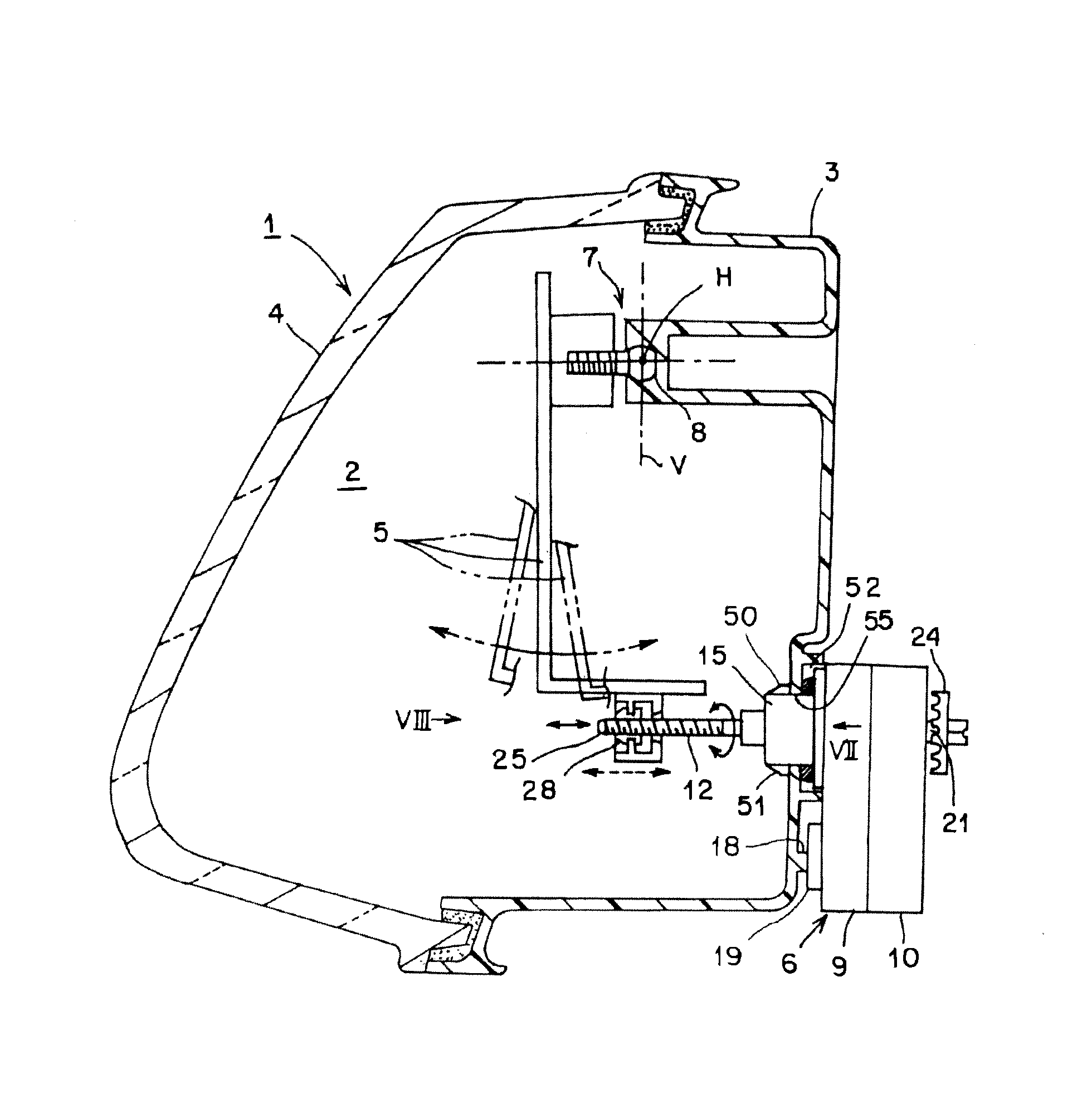
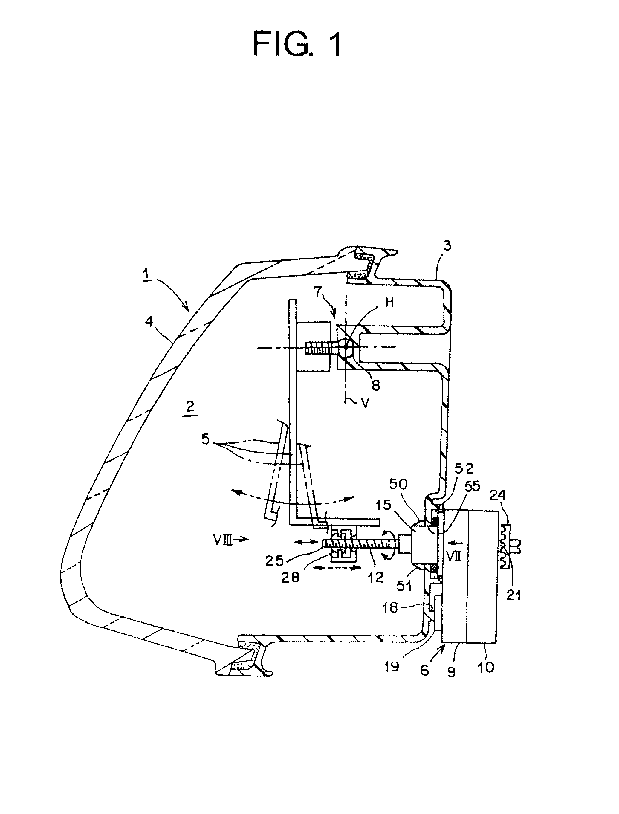
mount portion of a fixing member; the leveling device is mounted on the mount portion of the fixing member; and further, an abutment protrusive portion of the mount portion of the fixing member is allowed to abut against an abutment face protrusive portion of the housing of the leveling device, allowing the fixing member and the leveling device to be mounted in a stable manner without a backlash. A vehicle headlamp having the leveling device, of the present invention, is provided in such a manner that: an abutment face protrusive portion is provided partly of the housing, thus allowing the thickness of the housing to be increased at
a site of the abutment face protrusive portion and to be decreased at other sites. Therefore, the vehicle headlamp having the leveling device, according to the first aspect of the present invention, becomes capable of precluding a surface sink from occurring with an exterior face of the housing corresponding to the protrusive portion or rib, making it possible to preclude deformation of the exterior face of the housing, even with a case of having a protrusive portion or rib inside the housing. As a result, the vehicle headlamp having the leveling device, of the present invention, becomes capable of ensuring a stable distance between the mount portion of the fixing member and the housing of the leveling device, thus allowing the fixing member and the leveling device to be mounted in a stable manner without a backlash.
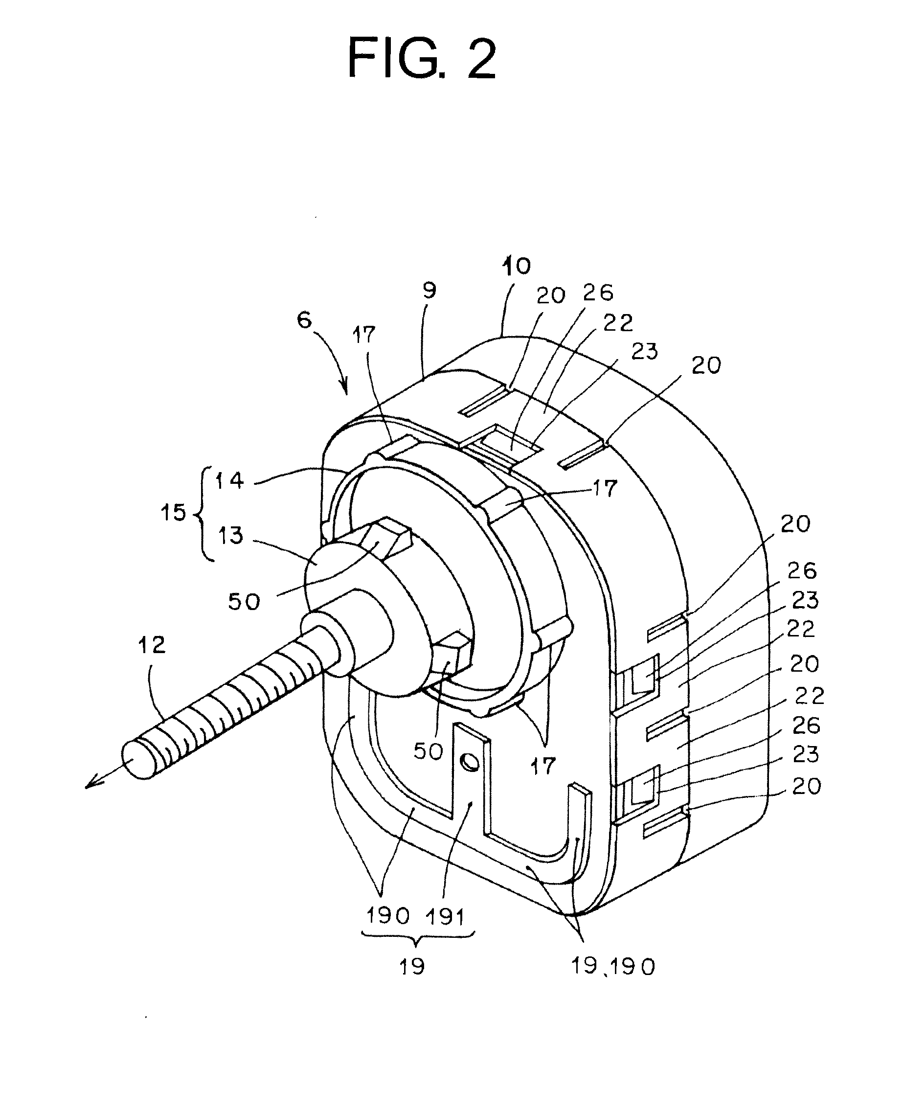
[0051]In addition, according to the second aspect of the present invention, an abutment face protrusive portion has a predetermined width, and is provided along a rim (outer circumference) of the housing, so that an abutment protrusive portion abutting against the abutment face protrusive portion can be provided in a range corresponding to the abutment face protrusive portion, i.e., at any position (site) in a wide range along the rim of the housing, of the mount portion of the fixing member. As a result, the vehicle headlamp having the leveling device, of the present invention, is provided in such a manner that the shape or
layout of the mount portion of the fixing member are different depending upon vehicle types, and even in a case where an abutment protrusive portion is provided at a different position of the mount portion of the fixing member, an abutment face protrusive portion which has a predetermined width and is provided along the rim (outer circumference) of the housing can suffice. In this manner, the vehicle headlamp having the leveling device, according to the second aspect of the present invention, allows the shared leveling device of one type to be compatible with a respective one of the fixing members of various vehicle types, so that manufacture or product management of the leveling device is simplified and cost reduction can be achieved accordingly.
[0053]In addition, according to the third aspect of the present invention, an abutment face protrusive portion has a predetermined width, and is provided on a vertical centerline of a housing, so that an abutment protrusive portion abutting against the abutment face protrusive portion can be provided in a range corresponding to the abutment face protrusive portion, i.e., at any position (site) in a wide range on the vertical centerline of the housing, of the mount portion of the fixing member. As a result, the vehicle headlamp having the leveling device, of the present invention, is provided in such a manner that the shape or
layout of the mount portion of the fixing member are different depending upon vehicle types, and even in a case where an abutment protrusive portion is provided at a different position of the mount portion of the fixing member, an abutment face protrusive portion which has a predetermined width and is provided on the vertical centerline of the housing can suffice. In this manner, the vehicle headlamp having the leveling device, according to the second aspect of the present invention, allows the shared leveling device of one type to be compatible with the fixing member of various vehicle types, so that manufacture or product management of the leveling device is simplified and cost reduction can be achieved accordingly.
