
Automatic lens double-face labeling machine

A labeling machine and lens technology, which is applied in the field of double-sided automatic labeling machines for lenses, can solve the problems of affecting production efficiency, prolonging the production cycle, and increasing production costs, so as to improve labeling efficiency, improve applicability, and facilitate assembly Effect

Pending Publication Date: 2018-04-10
SUZHOU SIPULANDI ELECTRONICS CO LTD
View PDF7 Cites 3 Cited by
  • Summary
  • Abstract
  • Description
  • Claims
  • Application Information

AI Technical Summary

Problems solved by technology

In the production process, it usually requires double-sided labeling of the lens according to customer needs, but the efficiency of double-sided labeling in the prior art is not high. For example, the patent application number 201420167966 discloses a double-sided automatic labeling In the marking machine, a vertical cylinder and a rotating motor are arranged between the support plates, and a gripper is provided on the rotating motor. By using the gripper to clamp the circuit board, the rotating motor can drive the circuit board to automatically turn over, avoiding The process of flipping the circuit board manually, but the production cycle is lengthened by rotating the circuit board with the rotating motor, which affects the production efficiency, and the configuration of the rotating motor and the gripper will increase the production cost
The patent with application number 201020622639.0 discloses a positioning double-sided labeling machine, which discloses a left labeling mechanism and a right labeling mechanism, but the two still need to be labeled separately, which affects production efficiency

Method used


Image

  • Automatic lens double-face labeling machine

Examples


Embodiment Construction

[0018] The present invention will be further described below in conjunction with the accompanying drawings and specific embodiments.

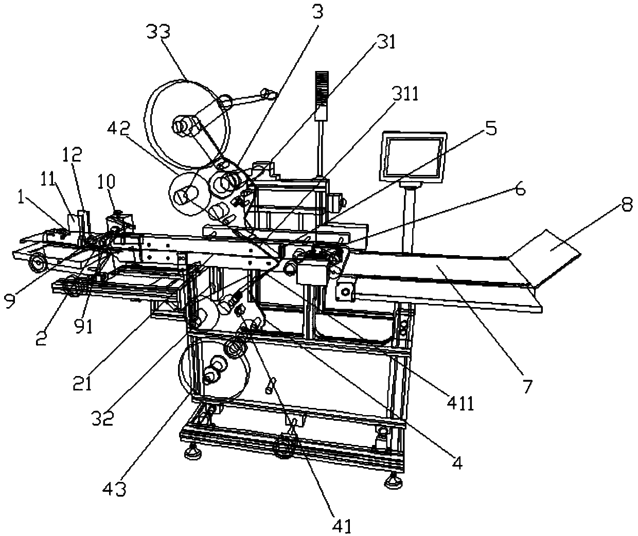
[0019] Such as figure 1 As shown, the double-sided automatic labeling machine for lenses includes a feeding mechanism 1 and a conveyor belt 2 connected to the feeding mechanism 1. An upper label transmission mechanism 3 is arranged above the conveyor belt 2. The upper label transmission mechanism 3 is provided with an upper The label transmission guide plate 311, the lower label transmission mechanism 4 is arranged under the conveyor belt 2, the lower label transmission mechanism 4 is provided with a lower label transmission guide plate 411, the angle between the upper label transmission guide plate 311 and the conveyor belt 2 is an acute angle, and the The upper label transport guide 311 and the lower label transport guide 411 are symmetrical with respect to the conveyor belt 2 . In order to facilitate labeling, the conveyor belt 2 near the u...


PUM


Abstract

The invention discloses an automatic lens double-face labeling machine. The automatic lens double-face labeling machine comprises a feeding mechanism and a conveying belt connected with the feeding mechanism. An upper label transmission mechanism is arranged above the conveying belt, and an upper label transmission guide plate is arranged on the upper label transmission mechanism. A lower label transmission mechanism is arranged below the conveying belt, and a lower label transmission guide plate is arranged on the lower label transmission mechanism. The included angle between the upper labeltransmission guide plate and the conveying belt is the acute angle. The upper label transmission guide plate and the lower label transmission guide plate are symmetric relative to the conveying belt.When a lens slides to the convergence position of the upper label transmission guide plate and the lower label transmission guide plate through the conveying belt, the upper label transmission mechanism labels the upper surface of the lens through the upper label transmission guide plate, meanwhile, the lower label transmission mechanism labels the lower surface of the lens through the lower labeltransmission guide plate, the double faces of the lens are synchronously labeled, and the labeling efficiency is improved.

Description

technical field [0001] The invention relates to a double-sided automatic labeling machine for lenses. Background technique [0002] With the rise and rapid development of the electronic machinery industry, the requirements for production efficiency are getting higher and higher in the process of processing. In the production process, it usually requires double-sided labeling of the lens according to customer needs, but the efficiency of double-sided labeling in the prior art is not high. For example, the patent application number 201420167966 discloses a double-sided automatic labeling In the marking machine, a vertical cylinder and a rotating motor are arranged between the support plates, and a gripper is provided on the rotating motor. By using the gripper to clamp the circuit board, the rotating motor can drive the circuit board to automatically turn over, avoiding The process of flipping the circuit board manually, but the production cycle is lengthened by rotating the ...

Claims


Application Information

Patent Timeline
IPC IPC(8): B65C9/18B65C9/40B65C9/36B65C9/02B65C9/32
CPCB65C9/02B65C9/1869B65C9/32B65C9/36B65C9/40
Inventor 潘桂斌
Owner SUZHOU SIPULANDI ELECTRONICS CO LTD
Features
  • Generate Ideas
  • Intellectual Property
  • Life Sciences
  • Materials
  • Tech Scout
  • Unparalleled Data Quality
  • Higher Quality Content
  • 60% Fewer Hallucinations
Learn More