Check patentability & draft patents in minutes with Patsnap Eureka AI!

Photoelectric meter fixing device

A technology for photoelectric detectors and fixing devices, which is applied in the direction of measuring devices, instruments, scientific instruments, etc., and can solve the problems of photoelectric detectors with large limitations, small functions, and low degree of automation of measuring devices.

Inactive Publication Date: 2018-04-10
成都图钉科技有限公司
View PDF0 Cites 0 Cited by
  • Summary
  • Abstract
  • Description
  • Claims
  • Application Information

AI Technical Summary

Problems solved by technology

[0003] However, the existing photoelectric detectors have relatively large limitations. They are generally hand-held and can only detect close-range objects. For long-distance measurements, when measuring with some more dangerous objects, the effect is very small. The conditions of use are limited, and the degree of automation of the measuring device is not very high

Method used


Image

  • Photoelectric meter fixing device
  • Photoelectric meter fixing device
  • Photoelectric meter fixing device

Examples


Embodiment Construction

[0018] The following will clearly and completely describe the technical solutions in the embodiments of the present invention with reference to the accompanying drawings in the embodiments of the present invention. Obviously, the described embodiments are only some, not all, embodiments of the present invention. Based on the embodiments of the present invention, all other embodiments obtained by persons of ordinary skill in the art without making creative efforts belong to the protection scope of the present invention.

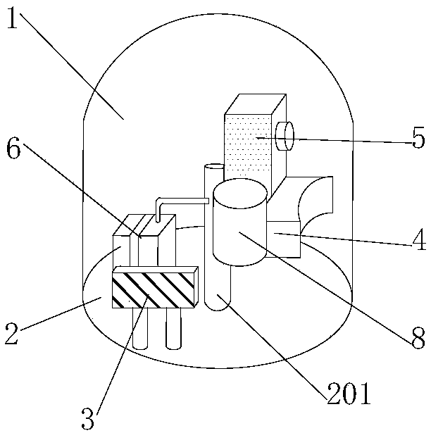
[0019] see Figure 1-3 , the present invention provides a technical solution: a photoelectric detector fixing device, including a device body 1 and a base 2, the bottom of the device body 1 is provided with a base 2, the base 2 is fixedly connected in the device body 1, and the device body 1 is provided with Alarm device 3, the alarm device 3 is fixedly connected in the device body 1, the middle part of the base 2 is provided with a fixed column 201, one end o...


PUM


Abstract

The invention discloses a photoelectric detector fixing device, which comprises a device body and a base. The bottom of the device body is provided with a base, and the base is fixedly connected in the device body. An alarm device is arranged inside the device body, and the alarm device is fixedly connected in the device body. The middle part of the base is provided with a fixed column, and one end of the fixed column is welded and arranged on the base. This kind of photoelectric detector fixing device has an electromagnetic telescopic rod on the right side of the fixed block, and one end of the electromagnetic telescopic rod is fixedly connected to the fixed block. It is emitted and irradiated to the detected object to cause light reflection, and then the unnecessary wave bands in the reflected light waves are filtered out by the light-incoming filter to prevent the messy light waves from affecting the calculation results.

Description

technical field [0001] The invention relates to the technical field of instrument fixing, in particular to a photoelectric detector fixing device. Background technique [0002] The so-called photoelectric detector includes: a housing, on the surface of which is provided with function keys, the function keys are connected to a microprocessor, and the microprocessor is respectively connected to a read-only memory, a display, and a light-emitting diode, and is characterized in that , a detection box is provided in the casing, a test paper holder is fixed in the box, a conductive optical fiber is provided between the test paper holder and the light-emitting diode, and a test paper holder is provided between the test paper holder and the phototransistor. There is a receiving optical fiber; the photosensitive triode is connected with the microprocessor through a preamplifying circuit, an amplifying circuit and an A / D converter. [0003] However, the existing photoelectric detecto...

Claims


Application Information

Patent Timeline
Patent Type & Authority Applications(China)
IPC IPC(8): G01N21/01
CPCG01N21/01
Inventor 李晴朝王伟
Owner 成都图钉科技有限公司
Features
  • R&D
  • Intellectual Property
  • Life Sciences
  • Materials
  • Tech Scout
  • Unparalleled Data Quality
  • Higher Quality Content
  • 60% Fewer Hallucinations
Learn More