A kind of civil water conductive wire

A conductive wire, civilian technology, applied to the parts of the conductive core, conductors, circuits, etc., can solve problems such as potential safety hazards, energy conservation and environmental protection, and potential threats to people, and achieve the effect of ensuring safe use

Active Publication Date: 2019-01-18
陈瑞
View PDF5 Cites 0 Cited by
  • Summary
  • Abstract
  • Description
  • Claims
  • Application Information

AI Technical Summary

Problems solved by technology

[0002] At present, it is known that the traditional electric wire is composed of a metal conductor and an insulating coat. The metal energy consumption is large, the cost is high, and it often causes a power fire. When the insulating coat is aging and broken, the risk of electric shock cannot be effectively prevented, and safety accidents occur, causing safety hazards. The difficulty of recycling waste wires is contrary to energy conservation and environmental protection

Method used


Image

  • A kind of civil water conductive wire
  • A kind of civil water conductive wire
  • A kind of civil water conductive wire

Examples


Embodiment 1

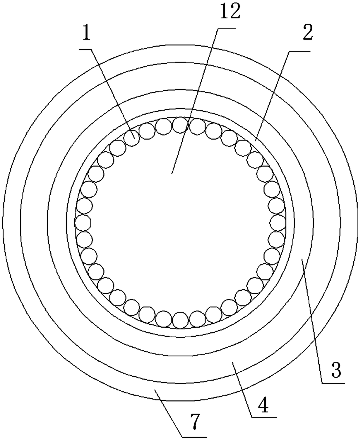
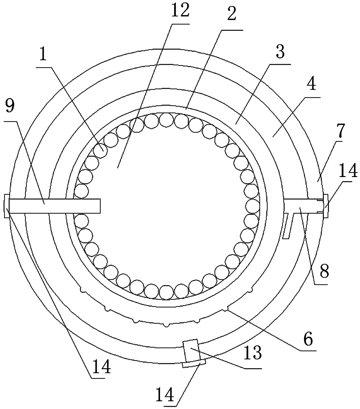
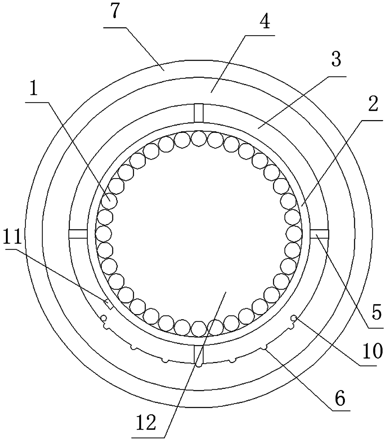
[0020] A kind of civil water conductive wire, its composition comprises: conductive core 1, described conductive core 1 is closely arranged on the inner surface of insulating layer 2, and described conductive core 1 forms circular cavity 12, and described circular cavity The body 12 is filled with a conductive solution, the outside of the insulating layer 2 is wrapped with an anti-corrosion fastening layer 3, and the outer end of the anti-corrosion fastening layer 3 is provided with a solution collection tank 4, and the solution collection tank 4 is made of stainless steel The frame 5 is connected to the anti-corrosion fastening layer 3, and a group of leakage holes 6 are arranged on the top surface of the bottom end of the solution collection tank 4, and the bottom end of the solution collection tank 4 is filled with a conductive solution neutralizing liquid, and the The outside of the solution collection tank 4 is provided with an insulating insulation layer 7.

Embodiment 2

[0022] A kind of civilian water conductive wire described in embodiment 1, the top of described solution collection tank 4 is connected with T-shaped liquid inlet pipe 8, and the lower end of described solution collection tank 4 is connected with discharge pipe 13;

[0023] The circular cavity 12 communicates with the outside through the inline tube 9 .

[0024] The inline pipe 9 , the T-shaped liquid inlet pipe 8 and the liquid discharge pipe 13 are all sealed by an insulating gasket 14 .

Embodiment 3

[0026] In the civil water conductive wire described in Example 1, a solution pH value sensor 10 is arranged outside the leakage hole 6, and the solution pH value sensor 10 transmits the detected analog signal to the filter amplification module, so The filter amplification module transmits the amplified analog signal to the A / D conversion module, the A / D conversion module transmits the digital signal to the single-chip microcomputer, and the single-chip microcomputer transmits the control signal to the memory and the wireless transmission module respectively, The wireless transmitting module transmits the wireless signal to the wireless receiving module, and the wireless receiving module transmits the signal to the display and the alarm respectively.

[0027] The filter amplification module, A / D conversion module, single-chip microcomputer, memory and wireless transmission module are all installed in the control box 11, and the control box 11 is arranged on the outer surface of ...


PUM


Abstract

The invention relates to a civilian water conductor wire. Conductive cores are closely arranged on the inner surface of an insulation layer; the conductive cores form a circular cavity; the circular cavity is internally equipped with a conductive solution; the insulation layer is externally wrapped an anti-corrosion fastening layer; the anti-corrosion fastening layer is externally provided with asolution collection tank; the solution collection tank is connected with the anti-corrosion fastening layer through a stainless steel frame; the bottom top surface of the solution collection tank is provided with a group of leakage holes; the bottom end of the solution collection tank is filled with a conductive solution neutralization solution; and the solution collection tank is externally provided with an insulated heat-insulation layer. The invention is used for the civilian water conductor wire.

Description

technical field [0001] The invention relates to a conductive wire for civil water. Background technique [0002] At present, it is known that the traditional electric wire is composed of a metal conductor and an insulating coat. The metal energy consumption is large, the cost is high, and it often causes a power fire. When the insulating coat is aging and broken, it cannot effectively prevent the risk of electric shock, and safety accidents occur, causing safety hazards. The difficulty of recycling waste wires is contrary to energy conservation and environmental protection. Contents of the invention [0003] The purpose of the present invention is to provide a conductive wire for civil water, which utilizes the principle of solution conduction and cooperates with a conductive core to help reduce the use of conductive metals and achieve the purpose of environmental protection and energy saving. [0004] Above-mentioned purpose realizes by following technical scheme: [00...

Claims


Application Information

Patent Timeline
Patent Type & Authority Patents(China)
IPC IPC(8): H01B7/00H01B7/32G01N33/00G01M3/00G08C17/02
CPCG01M3/00G01N33/00G08C17/02H01B7/0009H01B7/0027H01B7/328
Inventor 陈瑞
Owner 陈瑞
Why Eureka
Try Eureka