Charging and discharging equipment, method and device

A charging and discharging equipment and battery technology, applied in the electronic field, can solve the problems of affecting the service life of the battery, current backflow, damage to the battery, etc., and achieve the effect of avoiding current backflow and preventing current backflow

Active Publication Date: 2021-01-08
VIVO MOBILE COMM CO LTD
View PDF3 Cites 0 Cited by
  • Summary
  • Abstract
  • Description
  • Claims
  • Application Information

AI Technical Summary

Problems solved by technology

[0003] However, when multiple groups of graphene batteries are connected in parallel, there will be a problem of battery backflow between multiple batteries
For example, after using a terminal device with two batteries (the manufacturers or initial states of the two batteries may be different) for a period of time, the output voltage (or current) of one of the batteries drops significantly, so it is necessary to take out the battery for further use. Replace the battery with a new one. At this time, another battery left in the terminal device may be charged to a high voltage. If a new battery is connected to the terminal device, the battery charged to a high voltage and the newly connected battery will be separated. A large voltage difference will cause the high-voltage battery to impact the low-voltage battery with a large current, that is, the current backflow problem will occur, which will damage the battery and affect the service life of the battery.

Method used


Image

  • Charging and discharging equipment, method and device
  • Charging and discharging equipment, method and device
  • Charging and discharging equipment, method and device

Examples


Embodiment Construction

[0026] The following will clearly and completely describe the technical solutions in the embodiments of the present application with reference to the drawings in the embodiments of the present application. Obviously, the described embodiments are part of the embodiments of the present application, not all of them. Based on the embodiments in this application, all other embodiments obtained by persons of ordinary skill in the art without making creative efforts belong to the scope of protection of this application.

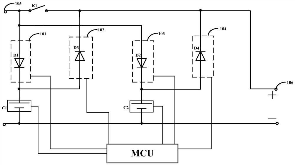
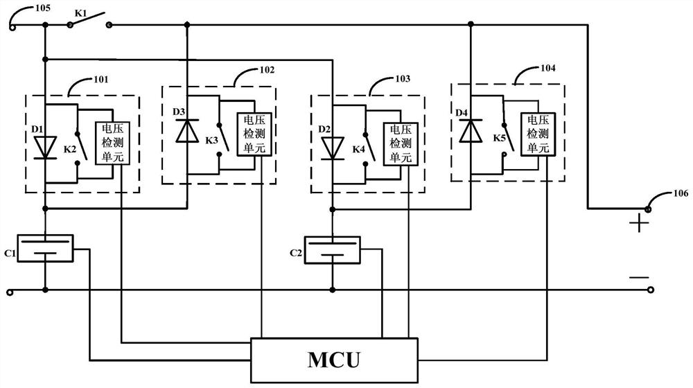
[0027] In one embodiment, a charging and discharging device includes an input terminal, a plurality of batteries connected in parallel, and an output terminal for connecting a load, and includes:

[0028] The first voltage detection module is connected between the battery and the output terminal, and includes a first diode, wherein the positive pole of the first diode is connected to the input terminal, and the negative pole of the first diode is connected to the po...


PUM


Abstract

The embodiment of the invention discloses charging and discharging equipment, a method and a device. The charging and discharging equipment comprises an input end, a plurality of batteries connected in parallel and an output end used for being connected with a load. The equipment further comprises a first voltage detection module, a second voltage detection module, a first switch, and a micro-control unit. The first voltage detection module is connected between the batteries and the output end and is composed of a first diode. The positive electrode of the first diode is connected to the inputend, and the negative electrode of the first diode is connected to the positive electrodes of the batteries. The second voltage detection module is connected between the batteries and the output endand is composed of a second diode. The positive electrode of the second diode is connected to the positive electrodes of the batteries, and the negative electrode of the second diode is connected to the output end. The first switch is connected between the input end and the output end. The micro-control unit is connected with the batteries, the first voltage detection module and the second voltagedetection module. By means of the equipment, the current back-flow problem between batteries can be effectively avoided.

Description

technical field [0001] The present application relates to the field of electronic technology, and in particular to a charging and discharging device, method and device. Background technique [0002] With the development of fast charging terminals such as smartphones and smart tablet computers, the capacity of batteries equipped with fast charging terminals will also become larger and larger. The battery charging experience just keeps getting worse. With the development of graphene batteries, high-voltage fast charging and low-voltage power supply of multiple groups of graphene batteries in parallel and in series have become the mainstream trend. [0003] However, when multiple groups of graphene batteries are connected in parallel, there will be a problem of battery backflow between multiple batteries. For example, after a terminal device using two batteries (the manufacturers or initial states of the two batteries may be different) is used for a period of time, the output...

Claims


Application Information

Patent Timeline
Patent Type & Authority Patents(China)
IPC IPC(8): H02J7/00
CPCH02J7/0024
Inventor 肖石文
Owner VIVO MOBILE COMM CO LTD
Why Eureka
Try Eureka