Metal tubular material surface wiping equipment

A tubular and metal technology, applied in the field of metal tubular material surface wiping equipment, can solve the problems of time-consuming and labor-intensive, unable to clean the material, and achieve the effect of quickly wiping the material and saving manpower

Inactive Publication Date: 2018-04-13
戚展鹏
View PDF2 Cites 3 Cited by
  • Summary
  • Abstract
  • Description
  • Claims
  • Application Information

AI Technical Summary

Problems solved by technology

[0006] In order to overcome the shortcomings of the existing wiping method, which is time-consuming and labor-intensive, and cannot wipe the material clean, the technical problem to be solved by the invention is to provide a surface wiping device for metal tubular materials that can quickly wipe the material and can wipe the material clean. equipment

Method used


Image

  • Metal tubular material surface wiping equipment
  • Metal tubular material surface wiping equipment

Examples


Embodiment 1

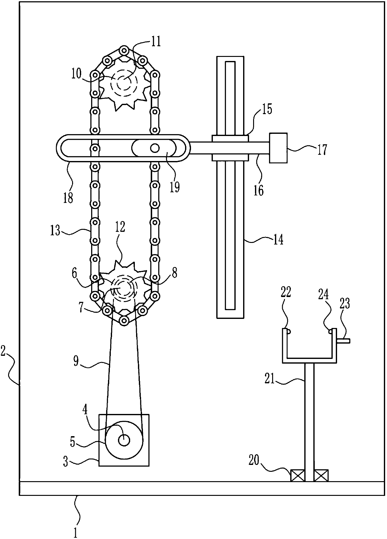
[0020] A device for wiping the surface of metal tubular materials, such as Figure 1-2 As shown, it includes a bottom plate 1, a mounting plate 2, a motor 3, a first rotating shaft 4, a large pulley 5, a first bearing seat 6, a second rotating shaft 7, a small pulley 8, a flat belt 9, a second bearing seat 10, the first Three rotating shafts 11, first gear 12, chain 13, slide rail 14, sliding block 15, connecting rod 16, friction block 17, moving frame 18, moving block 19, third bearing seat 20, fourth rotating shaft 21, frame body 22 , rotating rod 23 and rubber block 24, base plate 1 rear side is provided with mounting plate 2, and mounting plate 2 front side lower left parts are installed with motor 3, is connected with the first rotating shaft 4 on the output shaft of motor 3 front side, the first rotating shaft 4 The middle part is equipped with a large belt pulley 5, and the left part of the lower front side of the mounting plate 2 is provided with a first bearing seat 6...

Embodiment 2

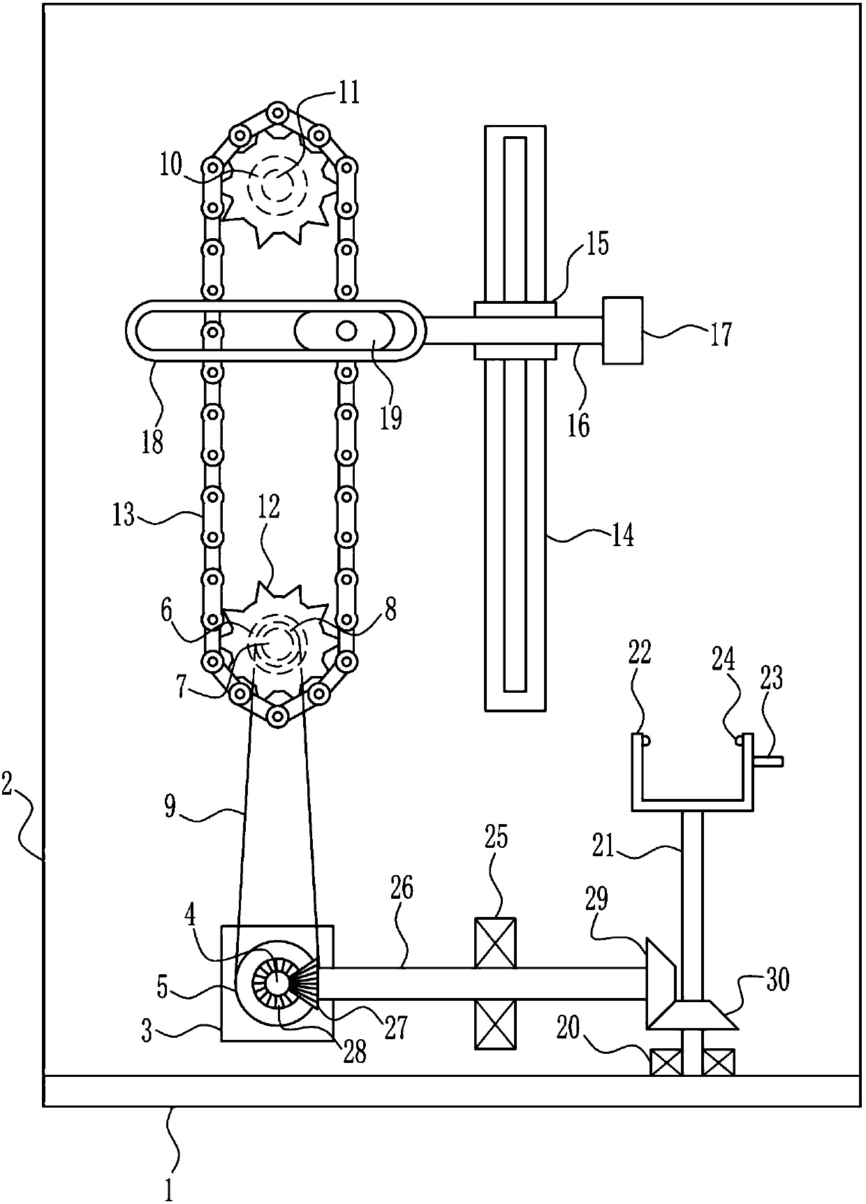
[0022] A device for wiping the surface of metal tubular materials, such as Figure 1-2 As shown, it includes a bottom plate 1, a mounting plate 2, a motor 3, a first rotating shaft 4, a large pulley 5, a first bearing seat 6, a second rotating shaft 7, a small pulley 8, a flat belt 9, a second bearing seat 10, the first Three rotating shafts 11, first gear 12, chain 13, slide rail 14, sliding block 15, connecting rod 16, friction block 17, moving frame 18, moving block 19, third bearing seat 20, fourth rotating shaft 21, frame body 22 , rotating rod 23 and rubber block 24, base plate 1 rear side is provided with mounting plate 2, and mounting plate 2 front side lower left parts are installed with motor 3, is connected with the first rotating shaft 4 on the output shaft of motor 3 front side, the first rotating shaft 4 The middle part is equipped with a large belt pulley 5, and the left part of the lower front side of the mounting plate 2 is provided with a first bearing seat 6...


PUM


Abstract

The invention relates to wiping equipment, in particular to metal tubular material surface wiping equipment. The metal tubular material surface wiping equipment can quickly wipe and clean materials. In order to solve the technical problem, the metal tubular material surface wiping equipment is provided. The metal tubular material surface wiping equipment comprises a bottom plate, a mounting plate,a motor, a first rotating shaft, a large belt wheel, a first bearing seat, a second rotating shaft, a small belt wheel, a second bearing seat, a third rotating shaft and the like. The mounting plateis arranged on the rear side of the bottom plate, the motor is arranged on the left part below the front side of the mounting plate, the output shaft on the front side of the motor is connected with the first rotating shaft, and the large belt wheel is arranged in the middle of the first rotating shaft. According to the metal tubular material surface wiping equipment, the effect that the materialscan be quickly and cleanly wiped can be achieved. A friction block can move up and down repeatedly by starting the motor to rotate clockwise, so that the friction block can quickly wipe and clean thematerials.

Description

technical field [0001] The invention relates to a wiping device, in particular to a metal tubular material surface wiping device. Background technique [0002] Metal material refers to the collective name of metal elements or materials with metal properties mainly composed of metal elements, including pure metals, alloys, intermetallic compounds of metal materials and special metal materials. The main forms of metal corrosion are uniform corrosion, galvanic corrosion, crevice corrosion and stress corrosion. Uniform corrosion refers to the uniform thinning of the cross-section due to the corrosion of the metal surface. Therefore, the annual average thickness loss value is often used as an indicator of corrosion performance. Steel generally corrodes uniformly in the atmosphere. In order to prolong the life of the metal, after the metal is rusted, the rust can be wiped off to prevent the rust from corroding the metal. [0003] The existing wiping method has the disadvantages ...

Claims


Application Information

Patent Timeline
Patent Type & Authority Applications(China)
IPC IPC(8): B08B9/023
CPCB08B9/023
Inventor 戚展鹏张释维赵硕
Owner 戚展鹏
Why Eureka
Try Eureka