
Sunken vertical lifting gate

A vertical lifting and gate technology, applied in the field of gates, can solve the problems of stuck garbage, water blocking of the gate body, increased load, etc., and achieves the effects of novel structure, energy saving and simple operation

Inactive Publication Date: 2018-04-13
杭州佧斯家居设计有限公司
View PDF0 Cites 3 Cited by
  • Summary
  • Abstract
  • Description
  • Claims
  • Application Information

AI Technical Summary

Problems solved by technology

[0002] Hydraulic flap gate - flap gate originally refers to the commonly used concrete structure hydraulic self-control flap gate in China. It is composed of multiple door leaves to form a large-span river barrage gate. The door body can rotate around the rollers, and use gravity and water pressure to control the operation of the concrete door body. By adding a hydraulic system, the passive opening and closing method of the hydraulic automatic control flap gate can be changed, and the opening and closing of the gate can be controlled manually. The hydraulic flap gate has the following defects: after the gate is fully opened, the door body of the hydraulic flap gate is lying in the water body of the river channel, and the door body has a serious water blocking phenomenon, and the lying body of the door body is easy to block floating objects (garbage jams) problem), causing the load to increase. In serious cases, objects hitting the gate will cause the flap gate to be washed away, and the reliability cannot be guaranteed, so that it cannot meet the needs of use. At the same time, the gate currently used also needs to drive the servo for small-scale drainage. Motor wastes energy, so a sunken vertical lift gate is proposed

Method used


Image

  • Sunken vertical lifting gate
  • Sunken vertical lifting gate
  • Sunken vertical lifting gate

Examples


Embodiment Construction

[0014] The following will clearly and completely describe the technical solutions in the embodiments of the present invention with reference to the accompanying drawings in the embodiments of the present invention. Obviously, the described embodiments are only some, not all, embodiments of the present invention. Based on the embodiments of the present invention, all other embodiments obtained by persons of ordinary skill in the art without making creative efforts belong to the protection scope of the present invention.

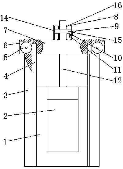
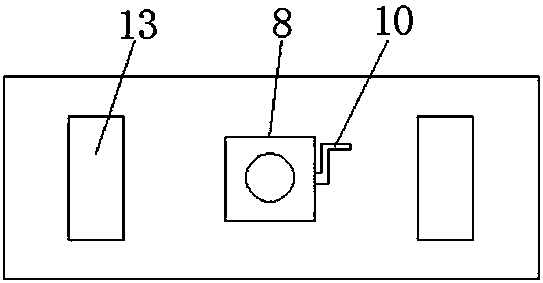
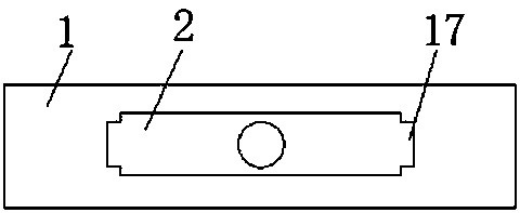
[0015] see Figure 1~3 , in an embodiment of the present invention, a sinking vertical lift gate includes a main gate 1, an auxiliary gate 2, a support column 3, a connecting plate 4, a lifting gear 5, a servo motor 6, a support frame 7, an outer box 8, Turntable 9, rotating shaft 10, pinion 11, screw rod 12, rectangular hole 13, lifting device 14, rocking bar 15, support block 16 and projection 17, the inside of described main gate 1 offers rectangular groove...


PUM


Abstract

The invention discloses a sunken vertical lift gate, which comprises a main gate, an auxiliary gate, a support column, a connecting plate, a lifting gear, a servo motor, a support frame, an outer box, a turntable, a rotating shaft, a pinion, a screw, and a rectangular hole. , lifting device, rocker, support block and bump, the inside of the main gate is provided with a rectangular slot, the inside of the rectangular slot is provided with an auxiliary gate, the middle position of the main gate is provided with a rectangular through hole, and the middle position of the top of the auxiliary gate is provided There are screw rods, connecting plates are provided on both sides of the main gate, supporting columns are respectively provided on both sides of the connecting plate, a notch is opened on the side of the supporting column close to the connecting plate, and the connecting plate is arranged inside the notch of the supporting column, A gear belt is provided on the side wall of the connecting plate facing the support column, a support frame is provided above the support column, two rectangular holes are arranged side by side in the vertical direction inside the support frame, and servo motors are respectively provided at both ends of the support frame.

Description

technical field [0001] The invention relates to the technical field of gates, in particular to a sunken vertical lift gate. Background technique [0002] Hydraulic flap gate - flap gate originally refers to the commonly used concrete structure hydraulic self-control flap gate in China. It is composed of multiple door leaves to form a large-span river barrage gate. The door body can rotate around the rollers, and use gravity and water pressure to control the operation of the concrete door body. By adding a hydraulic system, the passive opening and closing method of the hydraulic automatic control flap gate can be changed, and the opening and closing of the gate can be controlled manually. The hydraulic flap gate has the following defects: after the gate is fully opened, the door body of the hydraulic flap gate is lying in the water body of the river channel, and the door body has a serious water blocking phenomenon, and the lying body of the door body is easy to block floatin...

Claims


Application Information

Patent Timeline
IPC IPC(8): E02B7/26E02B7/36
CPCE02B7/26E02B7/36
Inventor 王亚茹
Owner 杭州佧斯家居设计有限公司
Features
  • Generate Ideas
  • Intellectual Property
  • Life Sciences
  • Materials
  • Tech Scout
  • Unparalleled Data Quality
  • Higher Quality Content
  • 60% Fewer Hallucinations
Learn More