Sand-filled expansion anchor rod

A technology of expanding bolts and bolts, which is applied in the installation of bolts, mining equipment, earthwork drilling and mining, etc., can solve the problems of bolt influence, bolt fracture, etc., to improve the anchoring force, increase the deformation margin, and realize The effect of effective support

Pending Publication Date: 2018-04-13
CHINA THREE GORGES UNIV
View PDF8 Cites 1 Cited by
  • Summary
  • Abstract
  • Description
  • Claims
  • Application Information

AI Technical Summary

Problems solved by technology

[0004] However, although the anchor rod provided by this patent solves the above-mentioned problems, for the anchor hole with a certain degree of curvature, the anchor rod cannot ensure that it fits the anchor hole completely tightly. Great impact, when the change is too large, it may even easily cause the anchor to break

Method used


Image

  • Sand-filled expansion anchor rod
  • Sand-filled expansion anchor rod
  • Sand-filled expansion anchor rod

Examples


Embodiment 1

[0056] When used for temporary support:

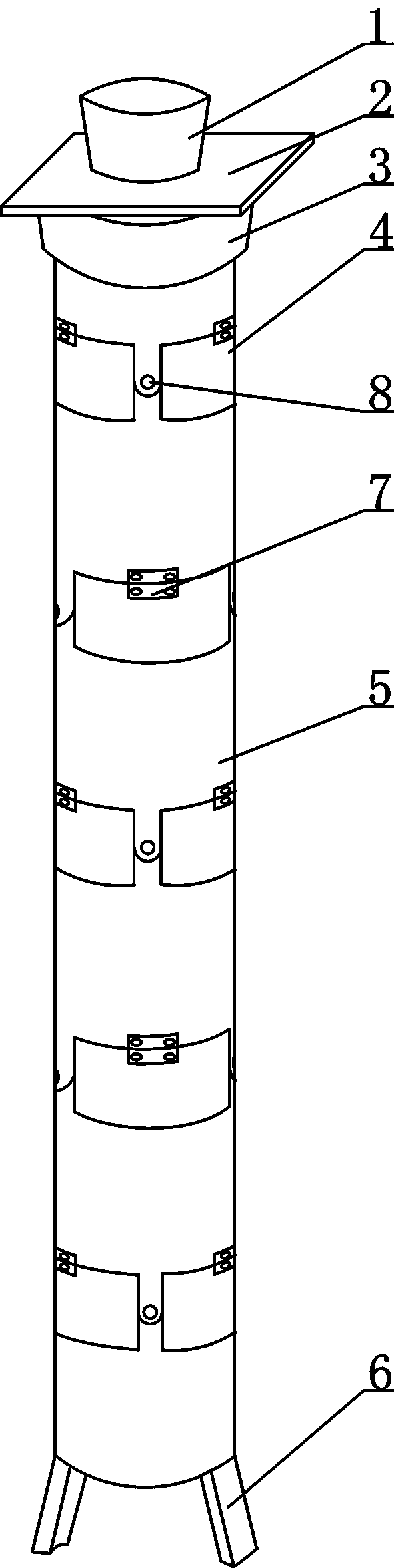
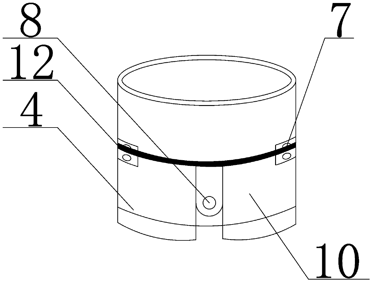
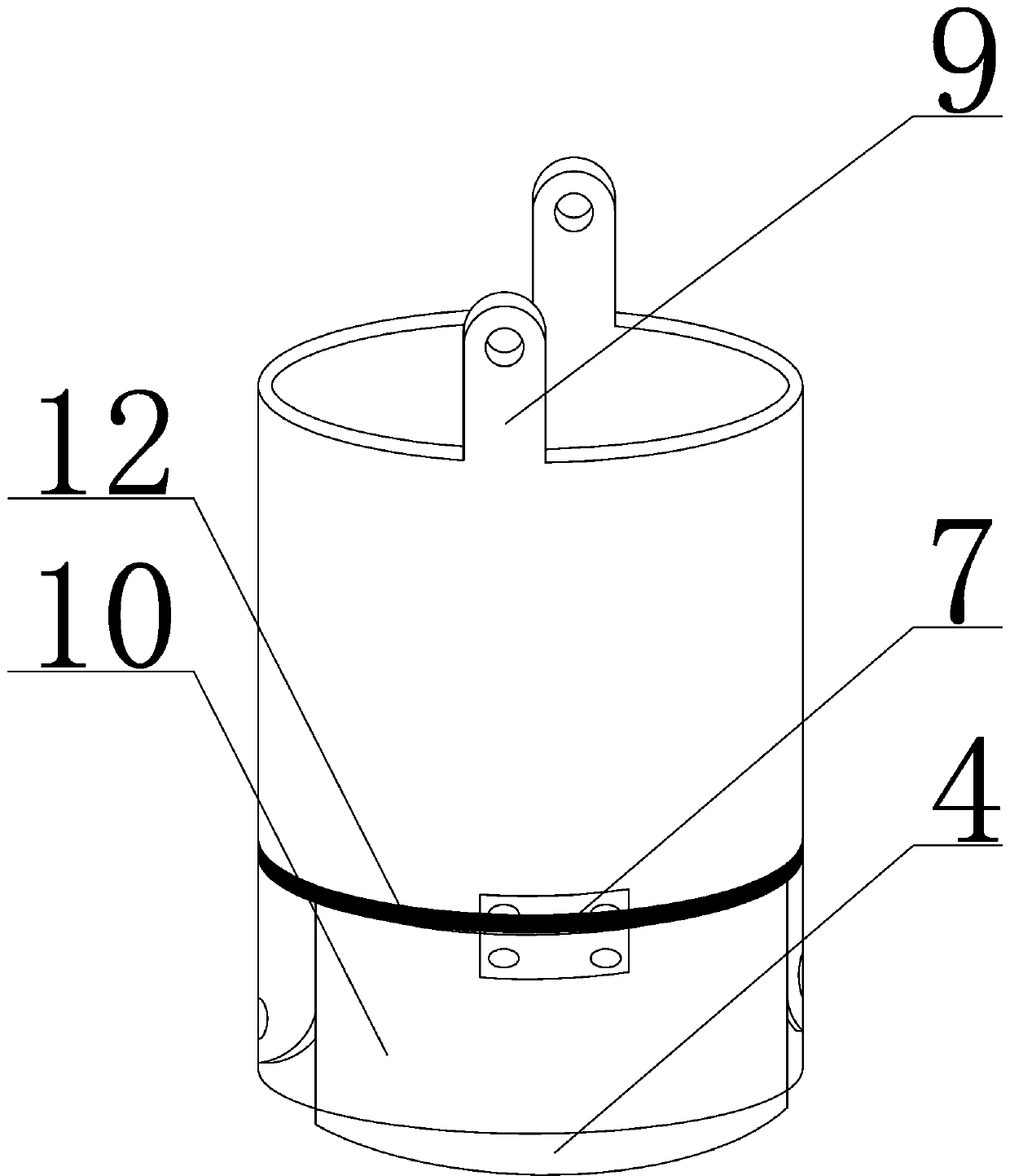
[0057] Install the anchor head on the anchor body, and then insert the anchor body with the installed anchor head into the hole wall. The insertion angle should be consistent with the inclination angle of the drilling hole. After being inserted, the anchor body is always in the center of the drilled hole. If the hole wall collapses, the hole should be drilled and cleaned again until the anchor can be inserted smoothly. After the anchor rod is installed in the borehole, install the sand stopper and the backing plate, connect the sand injection machine through the anchor rod, start the machine to inject sand, and the sand will flow into the anchor rod body, and the expansion window surface will be pushed back, and the expansion window surface will be opened. Open the anchor hole plugging piece, the anchor hole plugging piece expands from the initial cylindrical structure to form a circular truncated shape, the expansion window surface an...

Embodiment 2

[0059] When used for permanent support:

[0060] When the pressure of the surrounding rock of the tunnel is high and the tunnel is greatly affected by excavation, the surrounding rock is a weak rock formation and a broken zone, the tunnel is located in an unstable rock mass, and the weak surface of the surrounding rock is developed, the grouting process can be used for anchoring The operation is to pour the adjusted mortar into the pump, and under the action of the pressure device, the mortar is continuously sent into the anchor body, and then the backing plate is blocked with a plug to complete the anchoring operation.

[0061] By adopting the above structure, on the basis of the existing technology, the anchor rod can be bent in a small range, and the anchor rod can be deformed accordingly for the deformation of the anchor hole caused by the movement of the rock formation during the support process, avoiding the deformation of the anchor hole In the event that an external fo...


PUM


Abstract

A sand-filled expansion anchor rod comprises expansion windowing faces and a hollow anchor rod body. The hollow anchor rod body is composed of multiple sections of anchor rod main bodies; each sectionof anchor rod main body is provided with the two corresponding expansion windowing faces, wherein the upper edges of the expansion windowing faces are hinged to the lower edge of the anchor rod mainbody through hinges; a first lug plate is arranged between the expansion windowing faces at the lower edge of the anchor rod main body located at the topmost end; second lug plates are arranged at theupper edge of the anchor rod main body located at the middle section, and another first lug plate is arranged between the expansion windowing faces at the lower edge of the anchor rod main body located at the middle section; another second lug plates are arranged at the upper edge of the anchor rod main body located at the bottom end; the anchor rod main bodies are in hinged connection through the first lug plates and the second lug plates; and an anchor hole plugging piece is further arranged on the outer wall of the hollow anchor rod body, and connecting tubes are arranged on the top face of the anchor hole plugging piece and connected to a hoop on the outer wall of the hollow anchor rod body in a sleeving mode and can rotate around the hoop. By adopting the structure, it is ensured that the anchor rod is closely attached to an anchor hole, and the good support effect can be also achieved even for the anchor hole with a certain curvature.

Description

technical field [0001] The invention relates to the fields of tunnel support and slope protection, in particular to a sand-filled expansion bolt. Background technique [0002] Existing bolts are made of rigid materials, generally by filling an adhesive between the surrounding rock and the bolt, which not only has a long construction period, but also cannot compensate for changes in the anchor hole caused by rock formation movement. [0003] Among the existing patents, the invention patent application named "flexible injection pressure anchor rod with limited extension in the circular direction" application number is CN200610044390.8. Improvements have been made on the basis of the invention patent. While ensuring the original functions, the circumferential direction of the bolt body has been strengthened to avoid deformation such as creep due to the viscoelasticity or viscoplasticity of the polymer material of the rod body. When there are honeycomb pores in the soil pore wa...

Claims


Application Information

Patent Timeline
Patent Type & Authority Applications(China)
IPC IPC(8): E21D21/00
CPCE21D21/0006E21D21/0073E21D21/0093
Inventor 刘杰徐春霖李建林杨渝南王瑞红何建伟于振民
Owner CHINA THREE GORGES UNIV
Why Eureka
Try Eureka