[0024] The present invention will be further described below with reference to the accompanying drawings and specific embodiments, so that those skilled in the art can better understand and implement the present invention, but the examples cited are not intended to limit the present invention.
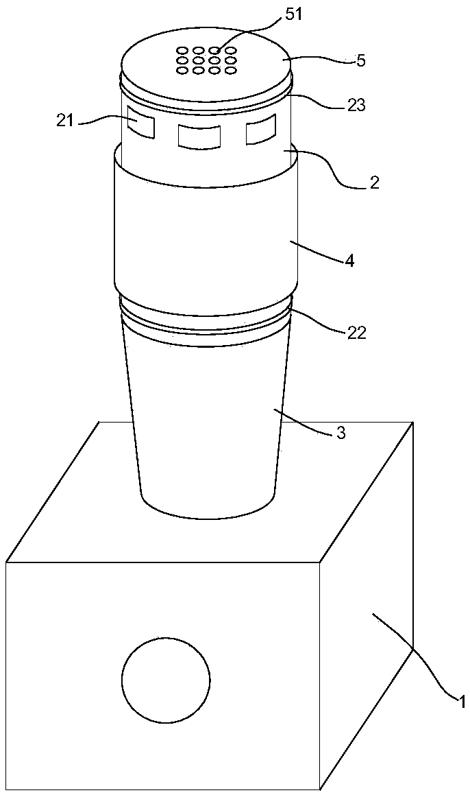
[0025] See figure 1 , The present invention discloses an air purifier with low noise and adjustable air volume, comprising a purifier body 1, an air supply channel arranged on the purifier body 1, and a fan (not shown) arranged in the air supply channel , Wherein the purifier body 1 is provided with a filter element, a humidifying component, etc., so that the air is filtered or humidified when passing through the purifier body 1. In order to facilitate later maintenance and maintenance, preferably, the air supply channel is detachably installed on the purifier body 1. In some embodiments, the air supply channel may also be permanently installed on the purifier body 1 in a fixed manner.
[0026] The air supply channel includes a first shell 2 having a columnar structure and an adjusting member 4. A cover plate 5 is provided on the top of the first shell 2 and a plurality of air outlets 21 are spaced on the outer wall of the first shell 2 The adjusting member 4 is also formed as a cylindrical structure, which is relatively screwed on the first housing 2 to completely shield, partially shield or completely expose each air outlet 21 at different rotation positions, thereby continuously Adjust the air outlet area of each air outlet 21. The air supply channel of the embodiment of the present invention can continuously adjust the air output of the air purifier to meet the requirements of different indoor environments for the air output.
[0027] In this embodiment, the adjusting member 4 is sleeved on the first housing 2, the inner wall of the adjusting member 4 is provided with internal threads, and the outer wall of the first housing 2 is correspondingly provided with external threads, and the adjusting member 4 is screwed to On the outer wall of the first housing 2. By rotating the adjusting member 4, the air outlet area of each air outlet 21 can be adjusted, and the accuracy of this way of adjusting the air volume is much higher than the traditional gear adjustment. If there is a higher requirement for adjustment accuracy, it can be achieved by reducing the thread pitch.
[0028] In this embodiment, in order to prevent the adjusting member 4 from being unscrewed from the thread, a first retaining ring 22 and a second retaining ring 23 are formed on the outer wall of the first housing 2 to perform adjustment on the upper and lower ends of the adjusting member 4. Limit. In some embodiments, the first retaining ring 22 and the second retaining ring 23 may be convex rings formed from the outer wall of the first housing 2 protruding outward. In other embodiments, the first retaining ring 22 and the second retaining ring 23 may be a plurality of stoppers arranged circumferentially on the outer wall of the first housing 2.
[0029] In some embodiments, the air outlet 21 may be opened on the cover plate 5 at the top of the air supply channel to increase the air outlet area and reduce the loss of air pressure. The air outlet 21 may be formed as a plurality of air outlets 51 arranged in a matrix. In order to reduce dust from entering the air supply channel, the air outlet 21 can be set as an opening and closing air outlet 21, such as a commonly used open and closing air outlet, which is closed when not in use.
[0030] See figure 2 , The first housing 2 includes a first barrier layer 24, a second barrier layer 25, and a third barrier layer 26 from the inside to the outside. A first cavity 271 is formed between the first barrier layer 24 and the second barrier layer 25. A cavity 271 is provided with a plurality of first partitions 27, and the first partitions 27 are configured such that the first cavity 271 is divided into a plurality of triangular-like cavities 272; between the second partition 25 and the third partition 26 A second cavity 281 is formed. A plurality of second partitions 28 are provided in the second cavity 281, and the second partitions 28 are configured such that the second cavity 281 is divided into a plurality of fan-shaped cavities 282.
[0031] In the working state, the noise emitted by the fan passes through the first interlayer 24 and the second interlayer 25 into the triangle-like cavity 272 and the fan annular cavity 282 in turn. After multiple reflections from the cavity, the energy of the sound wave Part of the loss occurs, and the part is absorbed and dissipated by the cavity, thereby reducing the noise of the fan and keeping the indoor environment quiet.
[0032] Since the sound wave has to undergo multiple reflections in the first cavity 271 and the second cavity 281, thereby causing energy loss, it is necessary to ensure that the first cavity 271 and the second cavity 281 have a certain thickness, but the thickness cannot be excessive. If it is too large, the thickness of the side wall of the air supply channel will be too large, which will affect the portability and aesthetics of the air purifier. As an exemplary embodiment, the thickness of the first cavity 271 and the second cavity 281 is 8-20 mm.
[0033] Preferably, in this embodiment, the two waists of the triangle-like shape are equal and the apex angle is 60°. This structure enables the sound waves to be reflected as much as possible after entering the triangle-like cavity 272, which increases the loss of sound wave energy and improves Muffling effect.
[0034] In order to increase the noise absorption effect of the side wall of the first housing 2, in this embodiment, the first barrier layer 24, the second barrier layer 25, and the third barrier layer 26 are provided with a sound insulation material filling layer 29. The filling layer 29 is preferably made of soundproof cotton or polyester fiber.
[0035] In this embodiment, the air supply channel further includes a second housing 3 located upstream in the air supply direction and connected to the first housing 2, and the second housing 3 is formed in a tapered structure with a gradually increasing cross section along the air supply direction . The second shell 3 with a tapered structure can guide the airflow into the first shell 2 without causing loss of wind pressure, which improves the air supply efficiency. Among them, the side wall structure of the second housing 3 is preferably consistent with the first housing 2.
[0036] In the air purifier of this embodiment, by rotating the adjusting member 4, the air outlet 21 on the first housing 2 can be completely shielded, partially shielded, or completely exposed, so that the area of the air outlet 21 and the air output can be continuously adjusted to Meet the requirements of indoor air purification;
[0037] Secondly, in the air purifier of this embodiment, the side walls of the air supply channel are arranged to include the first partition 24, the second partition 25, and the third partition 26 from the inside to the outside, the first partition 24 and the second partition. A first cavity 271 is formed between the partitions 25, a plurality of first partitions 27 are arranged in the first cavity 271, and the first partitions 27 are configured such that the first cavity 271 is divided into a plurality of triangular-like cavities 272; A second cavity 281 is formed between the second partition 25 and the third partition 26. A plurality of second partitions 28 are provided in the second cavity 281. The second partitions 28 are configured to separate the second cavity 281 into A plurality of fan ring cavities 282. The noise generated by the fan working through the first barrier 24 and the second barrier 25 enters into the triangle-like cavity 272 and the fan ring cavity 282 in turn. After multiple reflections from the cavity, part of the energy of the sound wave is lost, and part of the energy is lost. It is absorbed and dissolved by the cavity, thereby reducing the noise of the fan and keeping the indoor environment quiet.
[0038] The above-mentioned embodiments are only preferred embodiments for fully explaining the present invention, and the protection scope of the present invention is not limited thereto. Equivalent substitutions or alterations made by those skilled in the art on the basis of the present invention are all within the protection scope of the present invention. The protection scope of the present invention is subject to the claims.