Expansion valve
An expansion valve and valve core technology, applied in the field of expansion valves, can solve the problems of low flow control accuracy of the expansion valve, and achieve the effects of high flow control accuracy and small flow change.
- Summary
- Abstract
- Description
- Claims
- Application Information
AI Technical Summary
Problems solved by technology
Method used
Image

Examples
Embodiment 1
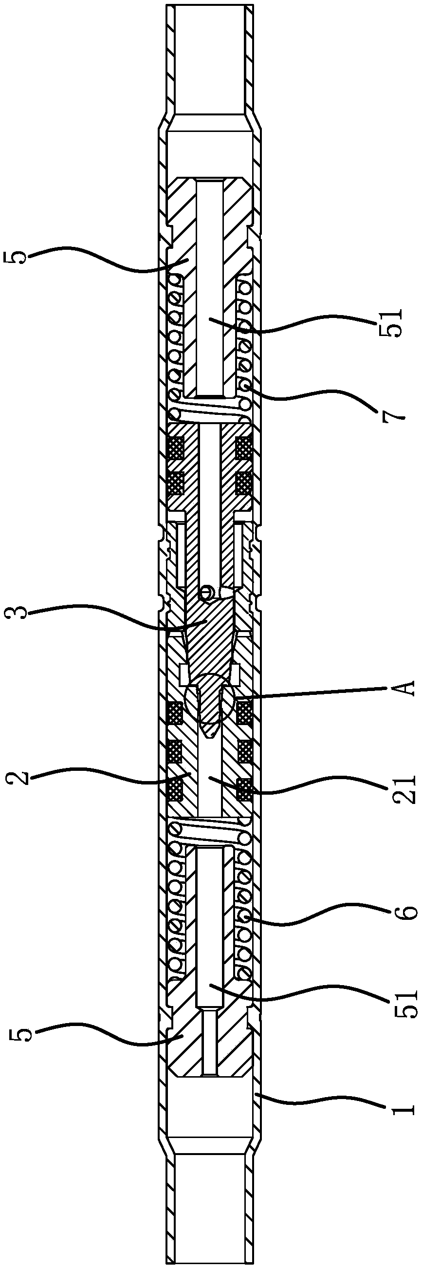
[0052] Such as figure 1 As shown, a two-way expansion valve includes a tubular valve body 1. A valve core 1 2 and a valve core 2 3 are slid inside the valve body 1. There are through holes 51 along the axial direction on the columns 5, and there are limit steps on the outer peripheral wall of the limit column 5. The spool one 2 and the spool two 3 are all located between the two limit columns 5, and the spool one 2 and A spring one 6 is arranged between a limit post 5, and one end of the spring one 6 leans against the spool one 2, and the other end leans against the limit step of the limit post 5, and the spool two 3 and the other limit A spring 2 7 is arranged between the position posts 5 , and one end of the spring 2 7 leans against the valve core 2 3 , and the other end leans against the limit step of another limit post 5 . combine figure 2 As shown, the spool one 2 has a through orifice 21 along the axial direction, the spool two 3 is columnar, and there is a columnar p...
Embodiment 2
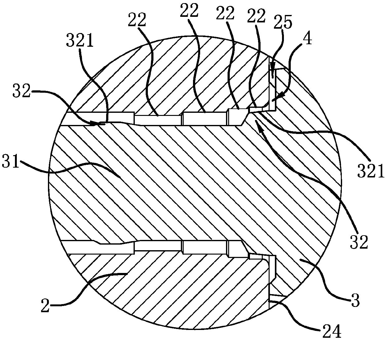
[0056] The structure of the expansion valve is basically the same as that of Embodiment 1, the difference is that Figure 9 , Figure 10 As shown, there are three throttling walls 321, three straight cylindrical surfaces 22, and the throttling part 32 extending to the end surface of the valve core 23 has two throttling walls 321, and the two throttling walls 321 are conical surfaces, and One end with a larger diameter of one throttling wall 321 is connected to the other end with a smaller diameter of the other throttling wall 321, and among the two conical throttling walls 321, the end of the throttling wall 321 near the end surface of the valve core 23 The taper is smaller than that of the other throttling wall 321 , and when the first valve core 2 and the second valve core 3 abut against each other, the two conical throttling walls 321 are opposite to the straight cylindrical surface 22 with the largest diameter.
[0057] When the passage of refrigerant is small or does not...
Embodiment 3
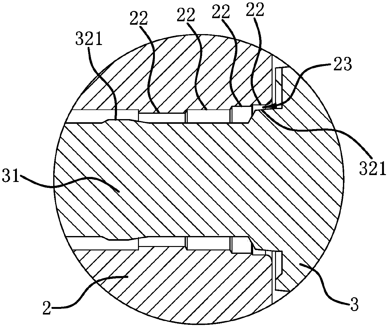
[0059] The structure of the expansion valve is basically the same as that of Embodiment 1, the difference is that Figure 16 , Figure 17 As shown, there are four throttling walls 321, there are two straight cylindrical surfaces 22, and the throttling part 32 extending to the end surface of the valve core 23 has two throttling walls 321, and the two throttling walls 321 are conical surfaces. , and one end of a throttling wall 321 with a larger diameter is connected to the other end of a throttling wall 321 with a smaller diameter, and among the two conical throttling walls 321, the throttling wall near the end surface of the valve core 23 The taper of 321 is smaller than that of the other throttling wall 321, and the other two throttling walls 321 are cylindrical surfaces. The largest straight cylindrical surface 22 is opposite, and the cylindrical throttle wall 321 with a larger diameter is opposite to the smaller diameter straight cylindrical surface 22. The cylindrical thr...
PUM
 Abstract
Description
Claims
Application Information
 - R&D
- Intellectual Property
- Life Sciences
- Materials
- Tech Scout
- Unparalleled Data Quality
- Higher Quality Content
- 60% Fewer Hallucinations
Browse by: Latest US Patents, China's latest patents, Technical Efficacy Thesaurus, Application Domain, Technology Topic, Popular Technical Reports.
© 2025 PatSnap. All rights reserved.Legal|Privacy policy|Modern Slavery Act Transparency Statement|Sitemap|About US| Contact US: help@patsnap.com