Combination valve

A combination valve and spool technology, applied in the field of combination valves, can solve problems such as increased operating load, difficulty in obtaining sealing, large-scale valve body of the driving part, etc., and achieves the effect of improving flow control accuracy

Active Publication Date: 2016-08-17
FUJIKOKI MFG CO LTD
View PDF7 Cites 0 Cited by
  • Summary
  • Abstract
  • Description
  • Claims
  • Application Information

AI Technical Summary

Problems solved by technology

Therefore, it becomes easy to cause an increase in the operating load, an increase in the size of the drive part (motor part) and the valve body, and there is also a problem that the size and shape of the second control valve for the small flow rate cannot be set to the optimum. It is suitable for small flow control, but it is not able to improve the flow control accuracy of small flow control, etc.
[0029] In addition, since the opening and closing of the first control valve for a large flow rate depends on the lift amount of the second spool which varies slightly, it is not uncommon for the first control valve for a large flow rate to fail to open and close at the desired timing. , In addition, when the small flow rate is controlled, since the refrigerant flows through the sliding surface gap of the first valve element, the back pressure chamber, and the pilot passage in sequence, there is also the following problem: it is easy to cause the small foreign matter mixed in the refrigerant to flow. The malfunction caused by it (for example, the gap between the sliding surface bites the tiny foreign matter and makes the first valve core stuck, etc.)
Therefore, in the valve-closed state, the pressure of the back pressure chamber of the large-flow control valve concentrates on a part of the annular lower end surface 127s of the pilot spool 127 through the pilot passage 119, and the pilot spool 127 tends to tilt. When the pilot spool 127 is tilted, as shown in FIG. 9(B), a gap β is formed between the annular lower end surface 127s of the pilot spool 127 and the bottom surface 121b of the second valve chamber 121, and the pressure in the back pressure chamber passes through the pilot valve. Passage 119 leaks to the side of the second valve chamber 121, which is likely to cause undesired actuation of the first valve element.
[0041] In addition, since the annular lower end surface 127s of the pilot valve body 127 is contacted and separated from the bottom surface 121b (the upper end opening edge of the pilot passage 119 ) of the second valve chamber 121, the pilot passage 119 (the upper end opening) is closed. Therefore, the contact pressure of the sealing surface (the annular lower end surface 127s and the bottom surface 121b) is relatively weak, and it is difficult to obtain the required sealing performance
In this case, in order to improve the sealing performance, countermeasures such as increasing the spring load of the pilot valve closing spring 126 and improving the machining accuracy of the sealing surface can be considered, but in any case there are problems in terms of cost (when increasing the pilot valve closing spring 126 When the spring load of the spring 126 is applied, a motor with a large driving torque must be used to move the pilot spool 127 up and down. In addition, it costs a considerable amount of money to improve the machining accuracy of the sealing surface.

Method used


Image

  • Combination valve
  • Combination valve
  • Combination valve

Examples


Embodiment Construction

[0111] Embodiments of the present invention will be described below with reference to the drawings.

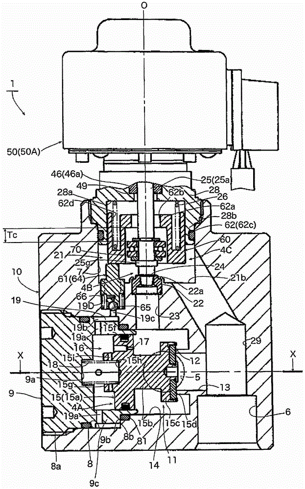
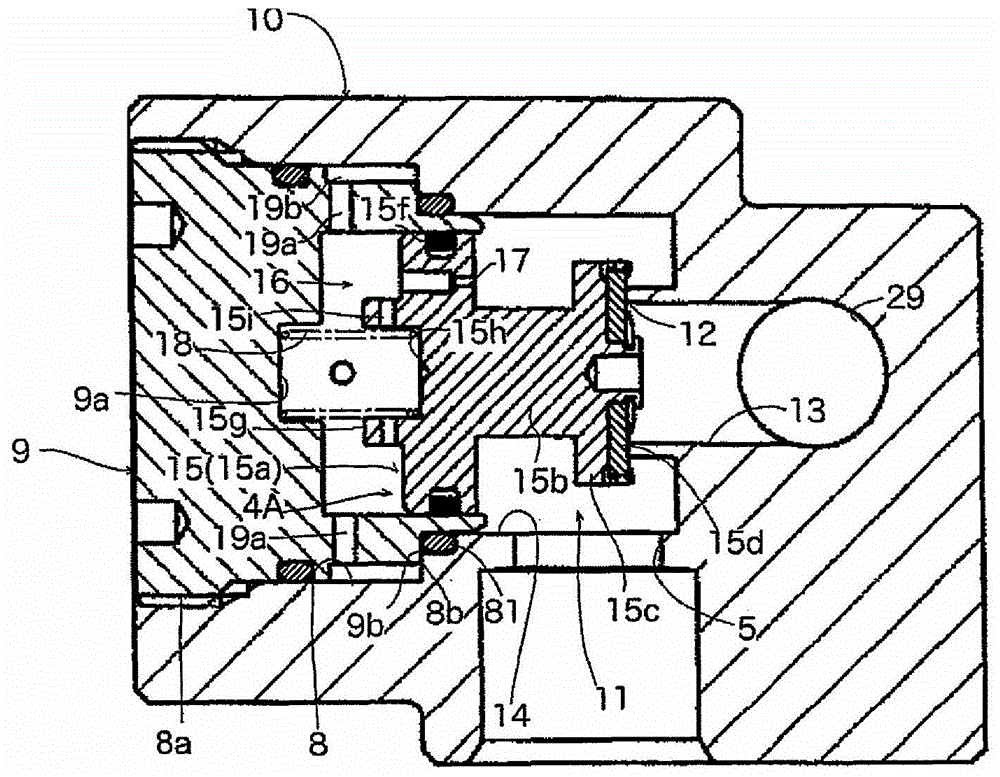
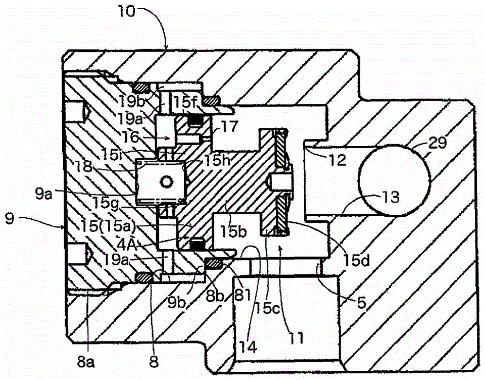
[0112] figure 1 , Figure 5 , Figure 7 It is a partial longitudinal sectional view showing an embodiment of the combination valve of the present invention, and each figure shows a different operating state. In addition, Figure 2(A) is figure 1 (the first control valve for large flow rate is in the closed state), the sectional view in the direction of arrow X-X, Fig. 2(B) is Figure 7 The sectional view in the direction of the Y-Y arrow (the first control valve for the large flow rate is in the open state). The internal structure of the stepper motor 50 part of the combination valve 1 of illustrated embodiment and Figure 11 The electric valve 1' of the prior art shown has the same structure, so only the outer shape of this part is shown. In addition, in each figure, the same as that shown in Figure 9 to Figure 11 The same symbols denote the same or equivalent parts. ...


PUM


Abstract

The invention provides a composite valve which can achieve both an improvement of a flow rate control precision in a small flow rate region and an increase of a controllable flow rate (a reduction of a pressure loss), and can enhance a sealing performance of a pilot passage by a pilot valve body, whereby it is possible to securely prevent a malfunction and it is possible to enhance a reliability. When a lift amount of a second valve body (24) for a small flow rate control is equal to or less than a predetermined amount (Tc), a pilot passage (19) is closed by a pilot valve body (60) which is slidable on an inner wall of a bush retention body (28), and a first valve port (13) is closed by a first valve body (15) for a large flow rate control, thereby taking a small flow rate control state in which a flow rate is controlled in correspondence to a lift amount of the second valve body (24). When the lift amount of the second valve body (24) goes beyond the predetermined amount (Tc), a pilot valve body (20) is raised in correspondence to a rising motion of a valve shaft (25) so as to open the pilot passage (19), thereby taking a large flow rate control state in which the first valve body (15) opens the first valve port (13). The pilot valve body (60) is outward inserted slidably to the valve shaft (25), and is energized downward by a spring member (26) so as to close the pilot passage (19). Further, when the lift amount of the second valve body (24) is increased more than the predetermined amount Tc, the pilot valve body (60) is caught on the valve shaft (25) so as to be pulled up.

Description

technical field [0001] The invention relates to a combination valve suitable for heat pump cooling and heating systems, and in particular to a pilot-operated combination valve with a large flow control valve and a small flow control valve. Background technique [0002] As a heat pump type cooling and heating system, a system including a compressor, a condenser, an evaporator, an expansion valve, and a four-way valve for switching (reversing) a refrigerant flow path is known. [0003] On the other hand, as a heat pump cooling and heating system for vehicles (such as for electric vehicles), for example, as described in Patent Document 1 figure 1 As can be seen, there has been proposed a system that additionally includes an expansion valve for cooling and an expansion valve for heating without reversing the flow of the refrigerant. [0004] In this system, since the flow of the refrigerant is not reversed, for example, when focusing on the figure 1 The expansion valve for hea...

Claims


Application Information

Patent Timeline
Patent Type & Authority Patents(China)
IPC IPC(8): F25B41/06F16K31/00
CPCF16K31/406F16K31/1245F16K31/42
Inventor 山下将司神尾猛荒井裕介
Owner FUJIKOKI MFG CO LTD
Why Eureka
Try Eureka