Electronic expansion valve

A technology of electronic expansion valve and valve body, which is applied in the direction of lifting valve, valve details, valve device, etc., can solve the problems of electronic expansion valve stuck, valve stem bouncing up and down, friction increase, etc., to improve flow control accuracy, flow rate The effect of high control precision and reduced friction

Pending Publication Date: 2019-09-13
ZHUJI YIBA ELECTRONICS VALVE
View PDF0 Cites 1 Cited by
  • Summary
  • Abstract
  • Description
  • Claims
  • Application Information

AI Technical Summary

Problems solved by technology

Therefore, the friction force on the entire execution structure will be greatly increased, which will eventually cause the electronic expansion valve to stick
[0004] The driving structure of the electronic expansion valve currently on the market is composed of a stepper motor stator, a coil and an executive component inside the valve body. The coil is basically customized, and the cost is relatively high, and the magnetic rotor in the executive component Made to order through high cost molds
[0005] Besides, the executive structure adopted by the current electronic expansion valve is a threaded screw mechanism. Since there must be a certain gap between the thread and the screw, otherwise the electronic expansion valve will be stuck because the threaded screw has no gap.
At the same time, due to the axial gap between the threaded screws, the valve stem will jump up and down, which will further cause the flow of the fluid to be unstable.

Method used


Image

  • Electronic expansion valve
  • Electronic expansion valve
  • Electronic expansion valve

Examples


Embodiment Construction

[0057] The technical solutions of the present invention will be further specifically described below through examples.

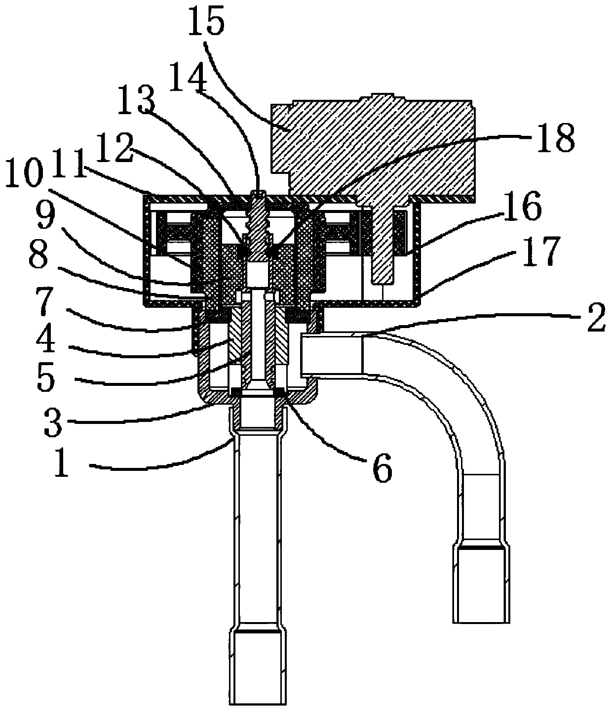
[0058] Such as figure 1 As shown, an electronic expansion valve includes a valve body assembly, an executive assembly and a driving structure.

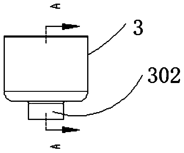
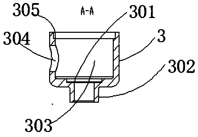
[0059] Among them, such as figure 2 , image 3 , Figure 8 As shown, the valve body assembly includes a valve seat 3, the axial lower part 302 of the valve seat 3 is welded with the B pipe 1, the valve seat side hole 304 is welded with the A pipe 2, and the valve seat 3 An annular channel 303 is formed inside, and the upper end surface of the annular channel 303 forms an inner step 305 of the valve seat, and the inner step 305 of the valve seat is welded together with the disc 702 on the flange 7, and the disc 702 is A stepped circle 703 is formed on the end surface, and the stepped circle 703 is welded together with the matching spacer sleeve 13 , and the outer diameter of the disc 702 is larger than that of t...


PUM


Abstract

The invention discloses an electronic expansion valve, in particular to the magnetic-coupling anti-clamping-stagnation electronic expansion valve with high flow control precision. The electronic expansion valve is characterized by comprising a valve body assembly, an execution assembly and a drive structure, wherein the valve body assembly comprises a valve seat; the lower part of the axial direction and the lateral direction of the valve seat are welded with a pipe B and a pipe A; a flange plate is welded to the upper end surface of the valve seat; and the upper surface of a tilting pan and an isolation sleeve pipe are welded together. The drive structure comprises a stepping motor, wherein a driving gear on an output shaft of the stepping motor drives a driven gear sleeved in the isolation sleeve pipe, and an outer magnetic ring on the driven gear drives an inner magnetic ring in the isolation sleeve pipe, so that the execution assembly is driven to rotate. The electronic expansion valve provided by the invention not only is excellent in performance, but also is low in cost.

Description

technical field [0001] The invention relates to an electronic expansion valve, in particular to an electronic expansion valve with magnetic coupling, stagnation prevention and high flow control precision. Background technique [0002] The electronic expansion valve is an important part in the refrigeration / heating system, mainly used to regulate the flow of fluid. The structure adopted by the electronic expansion valves currently on the market is basically the same, all of which are needle valve structures. The electronic expansion valve includes a stepper motor drive mechanism (stepper motor stator: coil and actuator components inside the valve body), an actuator structure (thread screw mechanism), a throttling structure (needle valve port) and some related structures. [0003] In the air conditioning system of the electronic expansion valve, the valve needle will generate axial pressure under high pressure, especially when the electronic expansion valve is in the closed s...

Claims


Application Information

Patent Timeline
Patent Type & Authority Applications(China)
IPC IPC(8): F16K31/04F16K31/06F16K1/02F16K1/32F16K1/36F16K1/42F25B41/06F25B41/35
CPCF16K31/04F16K31/0655F16K1/02F16K1/32F16K1/36F16K1/42F25B41/31Y02B30/70
Inventor 陈华军陈雨龙何孝水
Owner ZHUJI YIBA ELECTRONICS VALVE
Why Eureka
Try Eureka